 Pinomelean
There are many ways of building planar linkage mechanisms, and we all have used the simple approach of loosely fastening the joints with a bolt and nut, and maybe add washers in between.
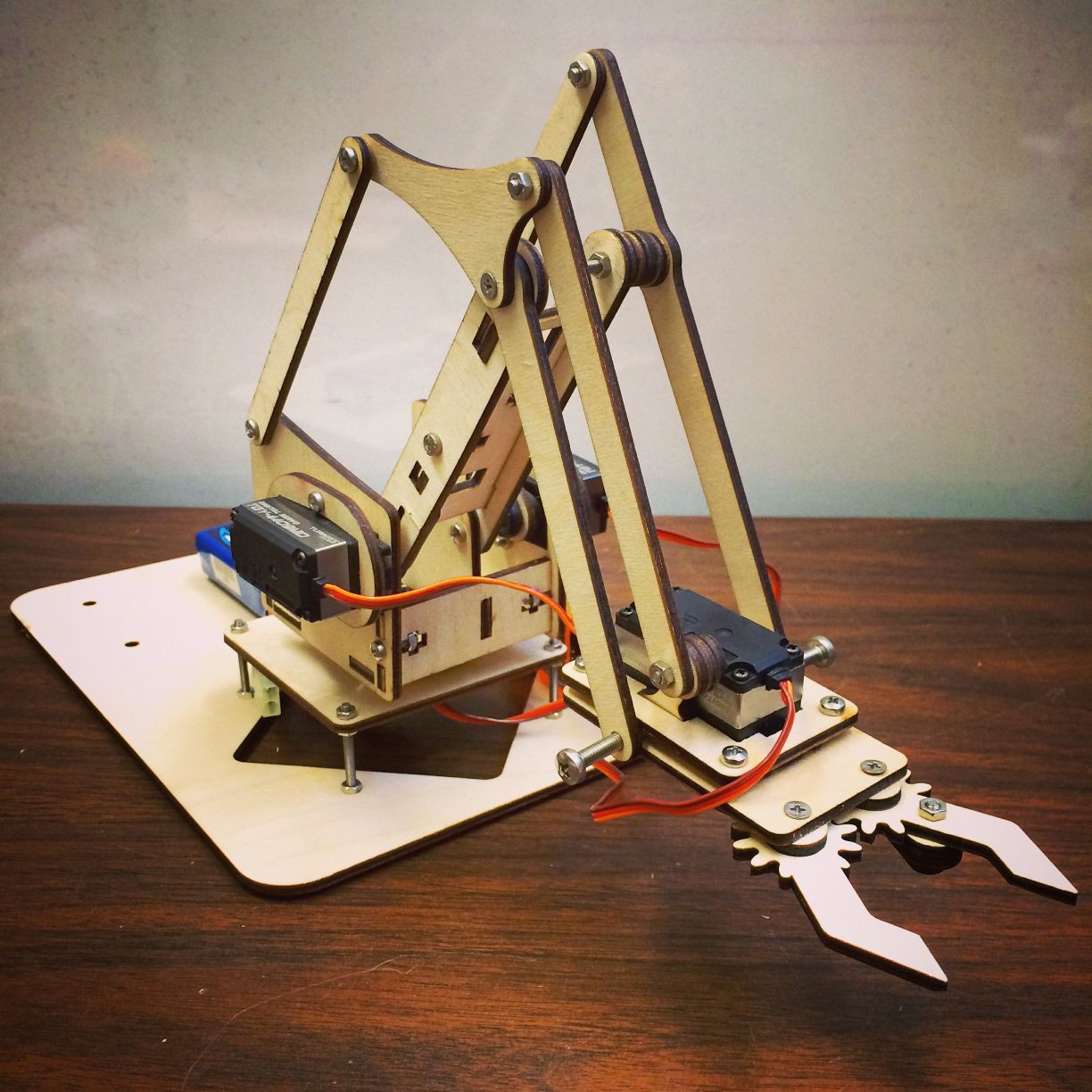
This technique is quite popular for building something simple and light duty, like the many DIY robot kits made out of laser cut acrylic or plywood, but it doesn't cut it for me. [No pun intended]
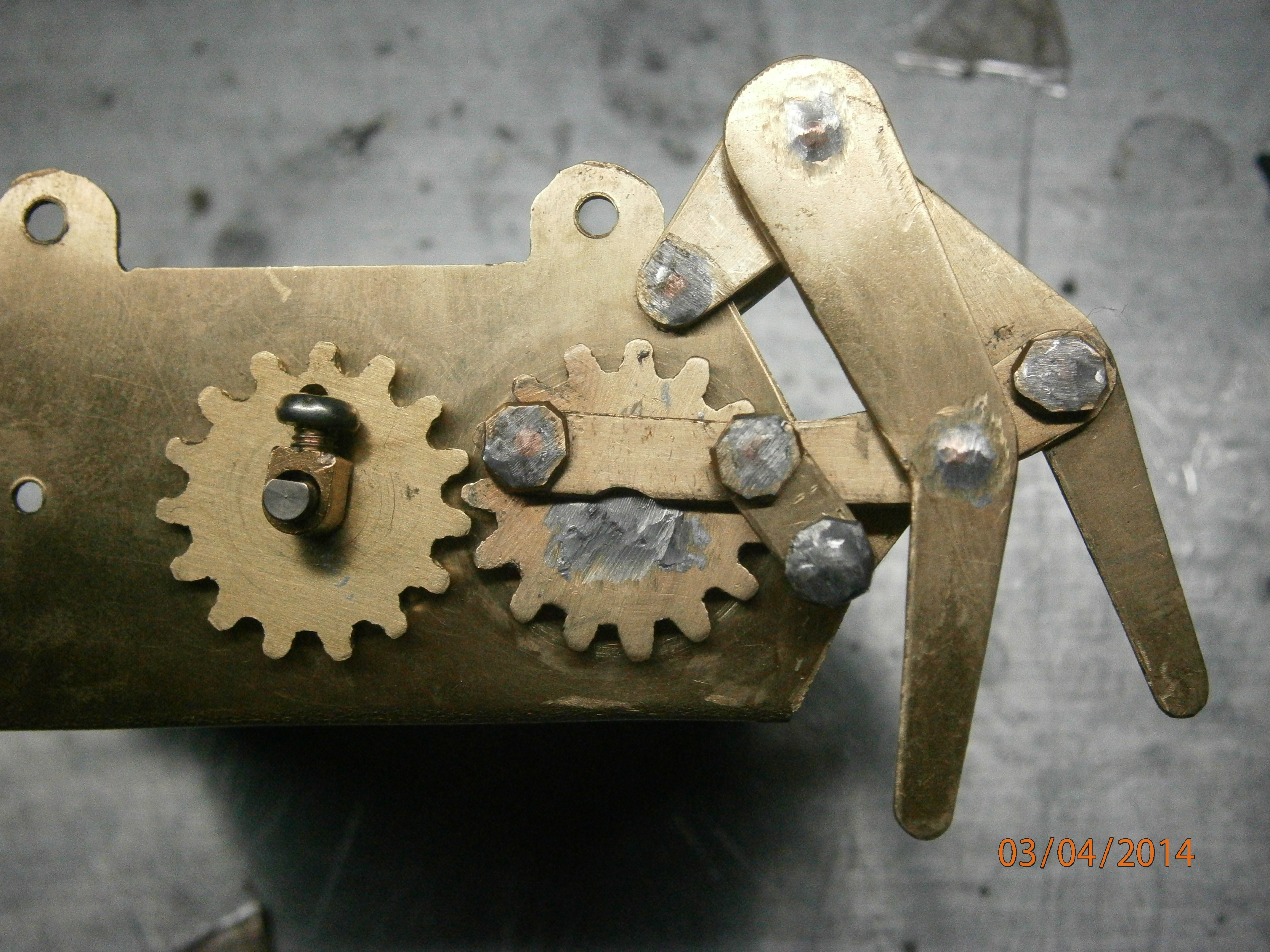
The joints are the most critical part of a mechanism such as this, as they will determine how well it can function, and will be the first places to fail due to wear if not built robust enough.
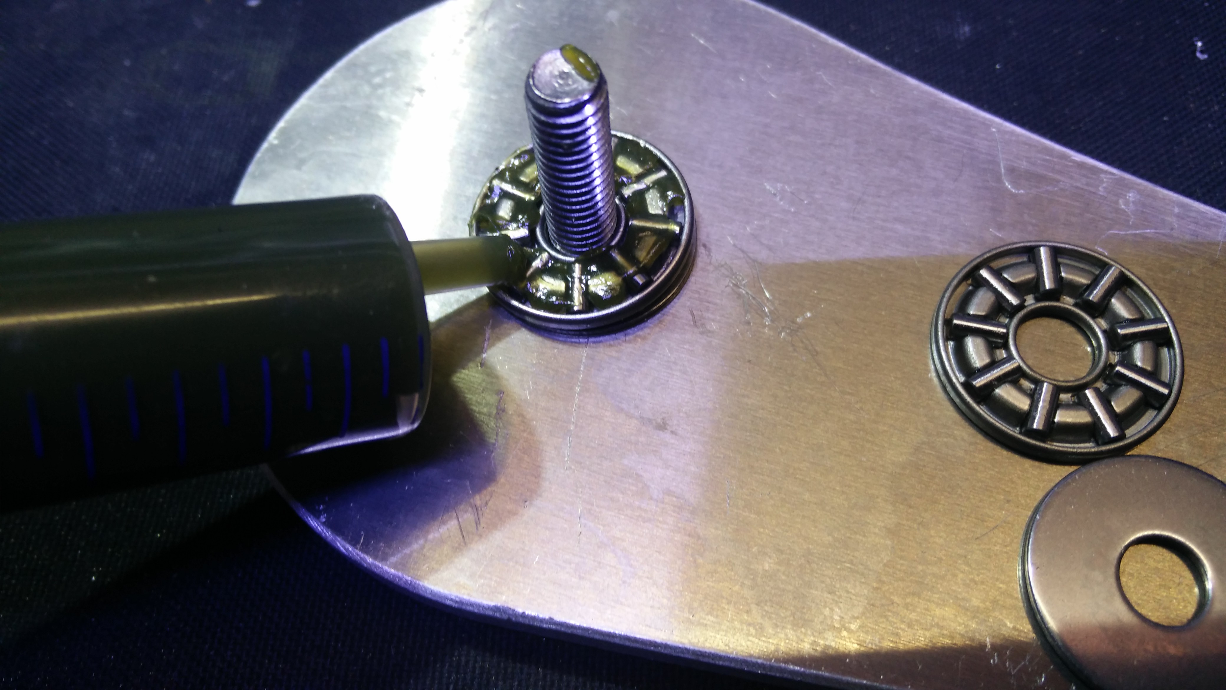
I decided to use stainless M6 bolts to act as axles in all joints, but i needed something to stop the parts from rubbing against each other.
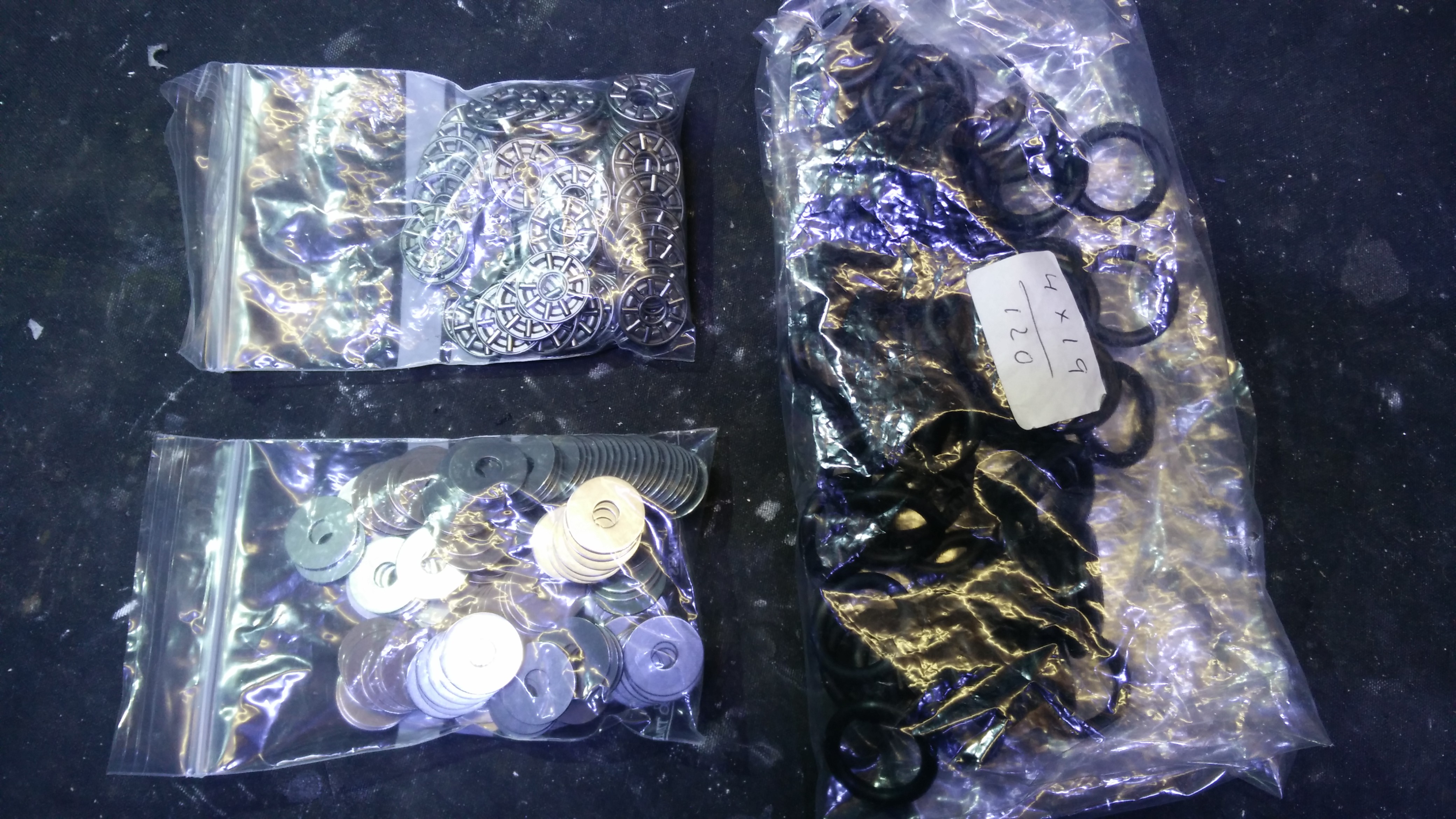
I decided to use axial bearings (AKA thrust bearings) for this task. I chose AXK 0619 roller bearings to suit the size of the axle, and i choose roller intead of ball bearings to keep the thickness down.
Since i wanted my robot to be all-terrain, and the roller bearings are open by design, i needed to consider ways of limiting particle and water ingress in them.
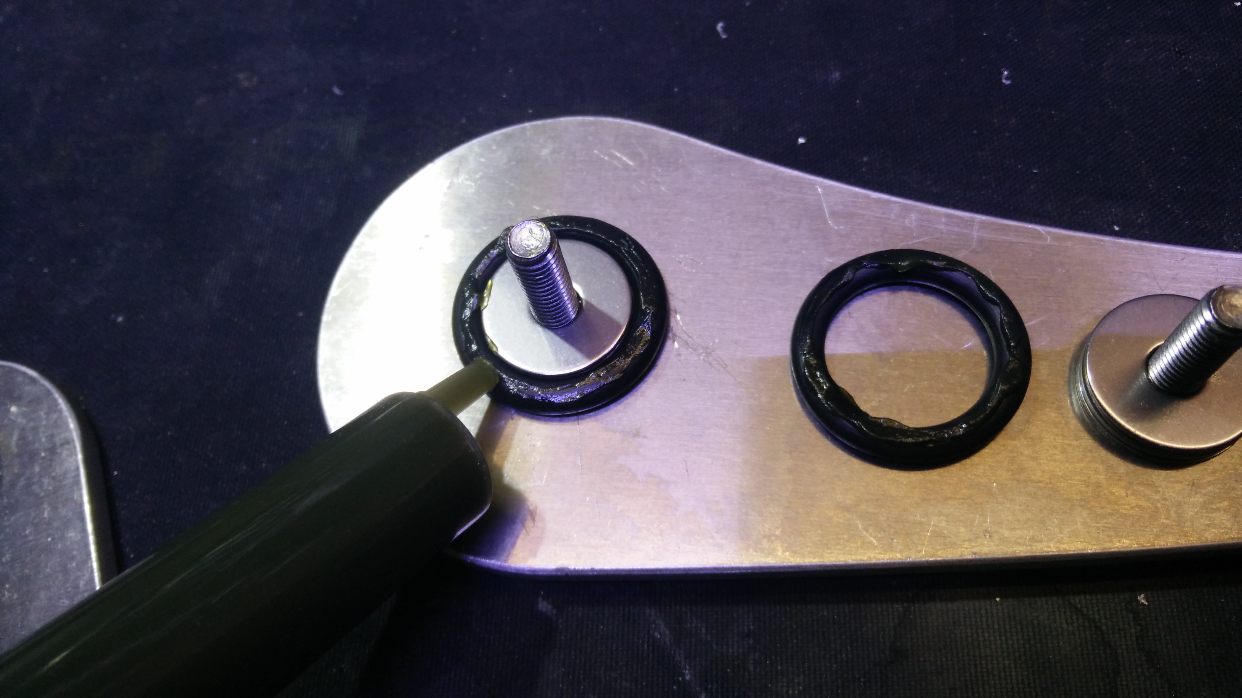
So i bought a bunch of o-rings of the same thicknes (4mm) and a fitting internal diameter for all the bearings (19mm).
 Putting the o-rings around the bearings will prevent particle ingress, and coating them with grease will make the assembly waterptoof.
I begin building by screwing in tight the bolts in the threaded parts. The bolts have to be button head because any other kind of M6 head is thicker than the 4mm of separation between parts that the bearings provide.
 The thrust bearings came with a light oil coating. That has to be cleaned, and the bearings then packed with grease. The bearings are composed of two washers and the cage with the rollers, so the cage has to be installed between washers.
 Each bearing gets an o-ring around it, which is greased both so it won't rub with the aluminium parts, and to prevent water ingress.
 The parts that complete each joint are placed on the bearings, and new bearings are placed on them. Before doing so, it's a good idea to apply grease to the part of the bolt that will be in contact with the joint parts.
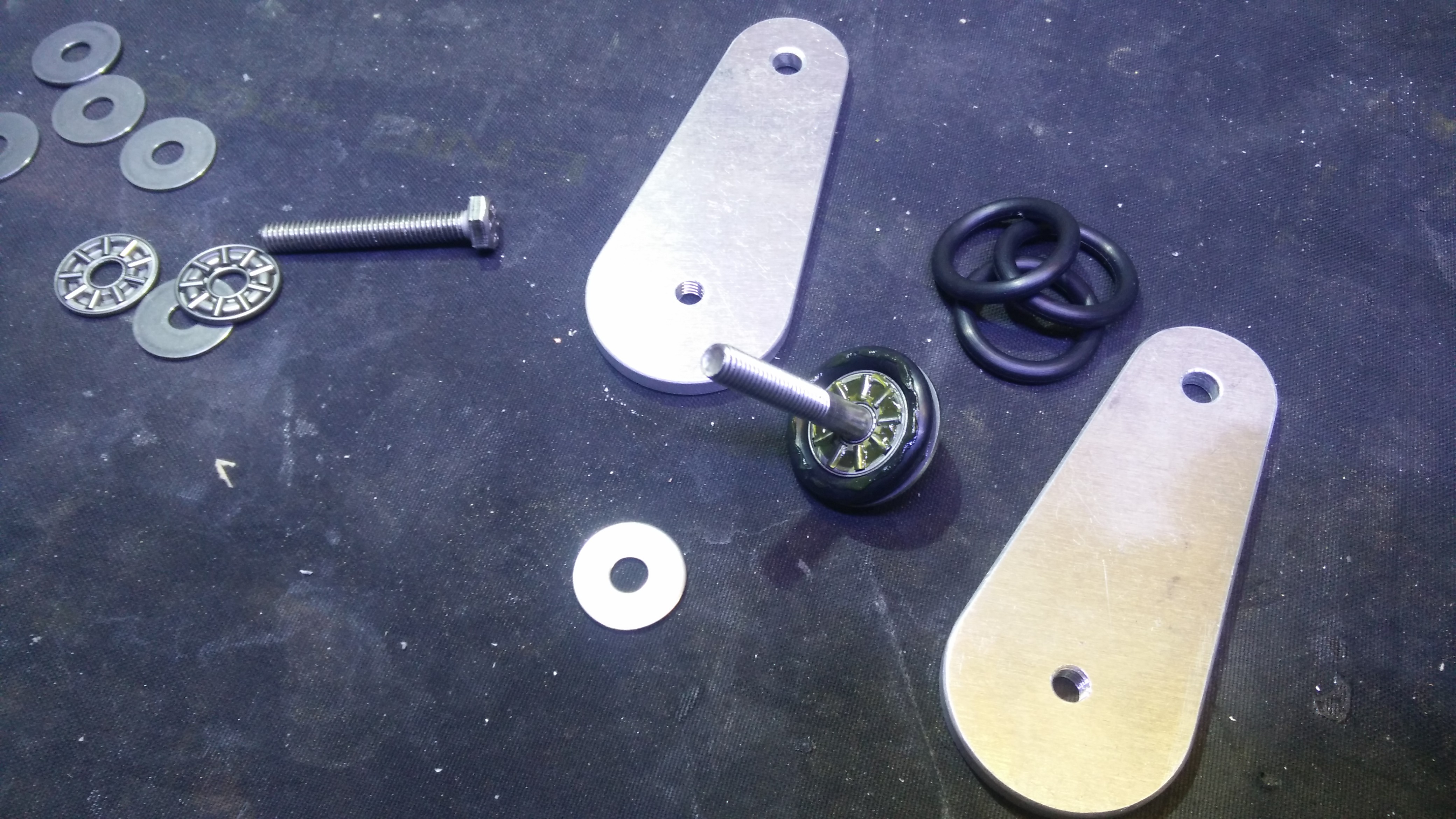
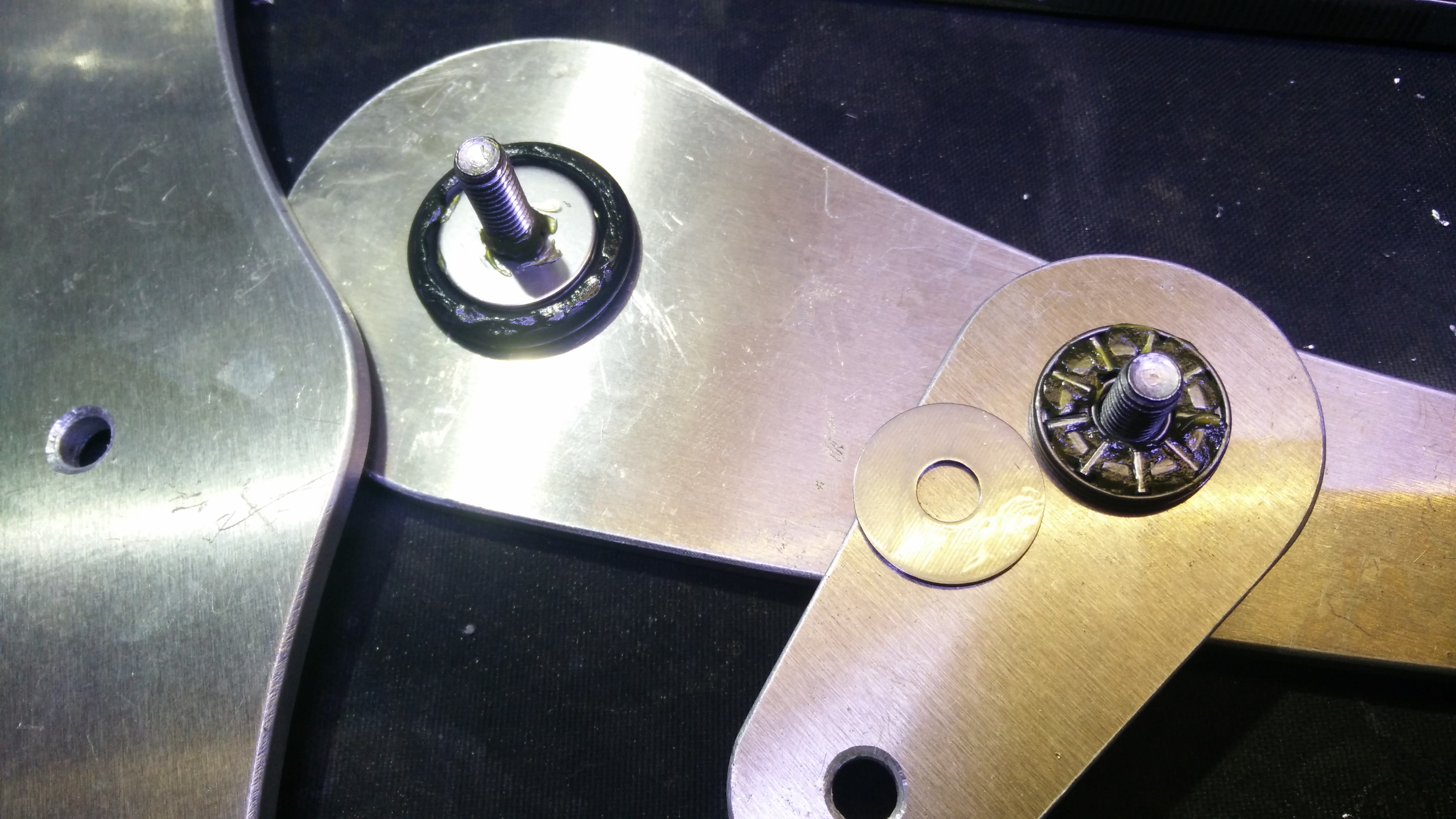 To finish each joint, a big washer is placed over the bearings and o-rings to close and hold them in place.
The washers that i'm using are actually laser cut from 1mm stainless sheet, and 27mm in outer diameter.
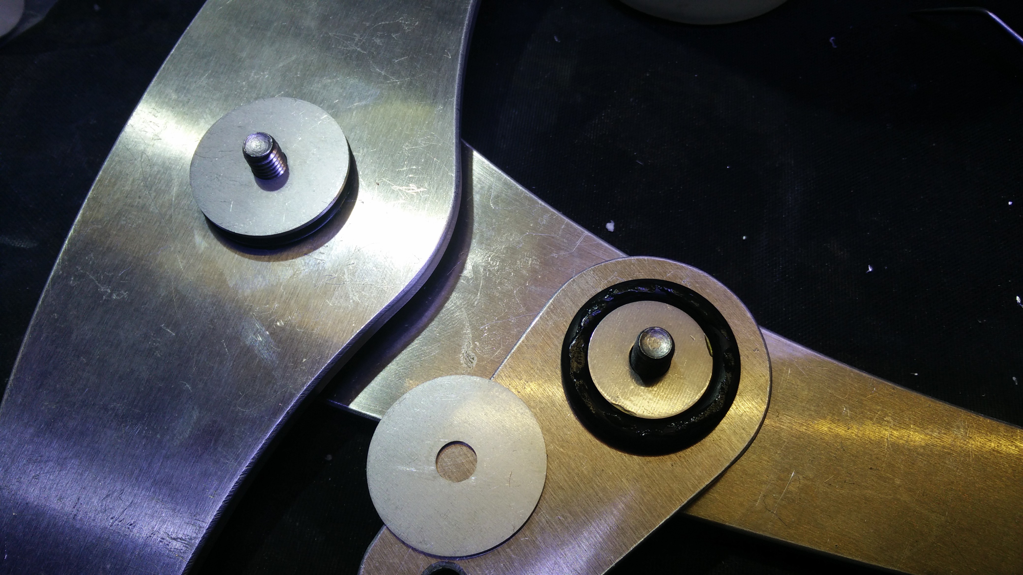 A nylon-insert lock nut (also stainless) is installed on each joint, tightened enough to keep the parts parallel against the bearings, but not so much that the joint become hard to turn.
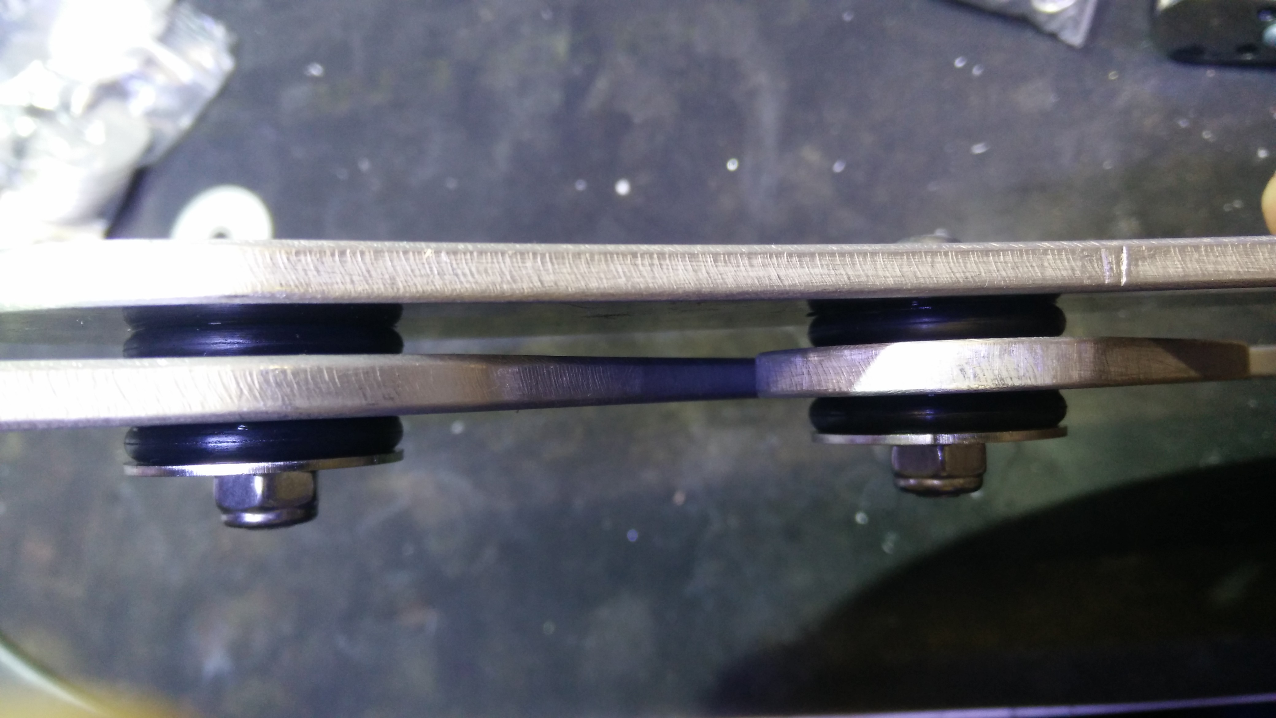
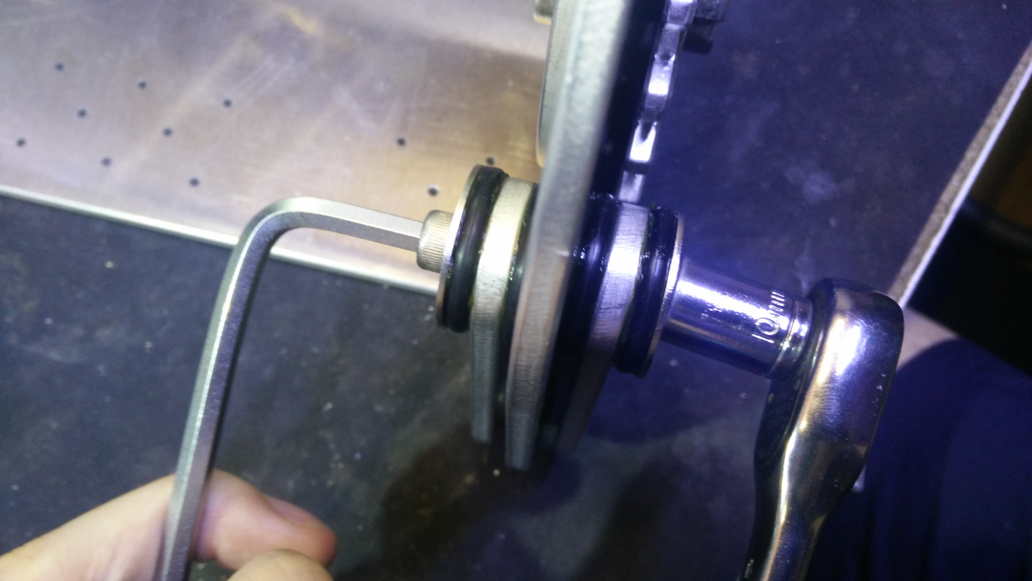
 This is what the hardware sandwich looks like from the side, The o-rings completely cover the bearings from dirt, and the grease lubricates them and keeps moisture out.
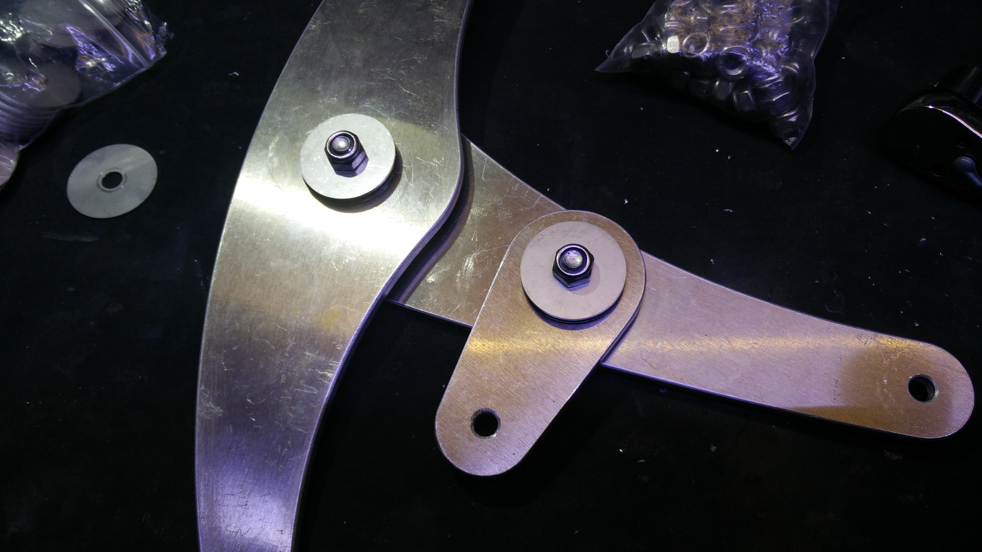
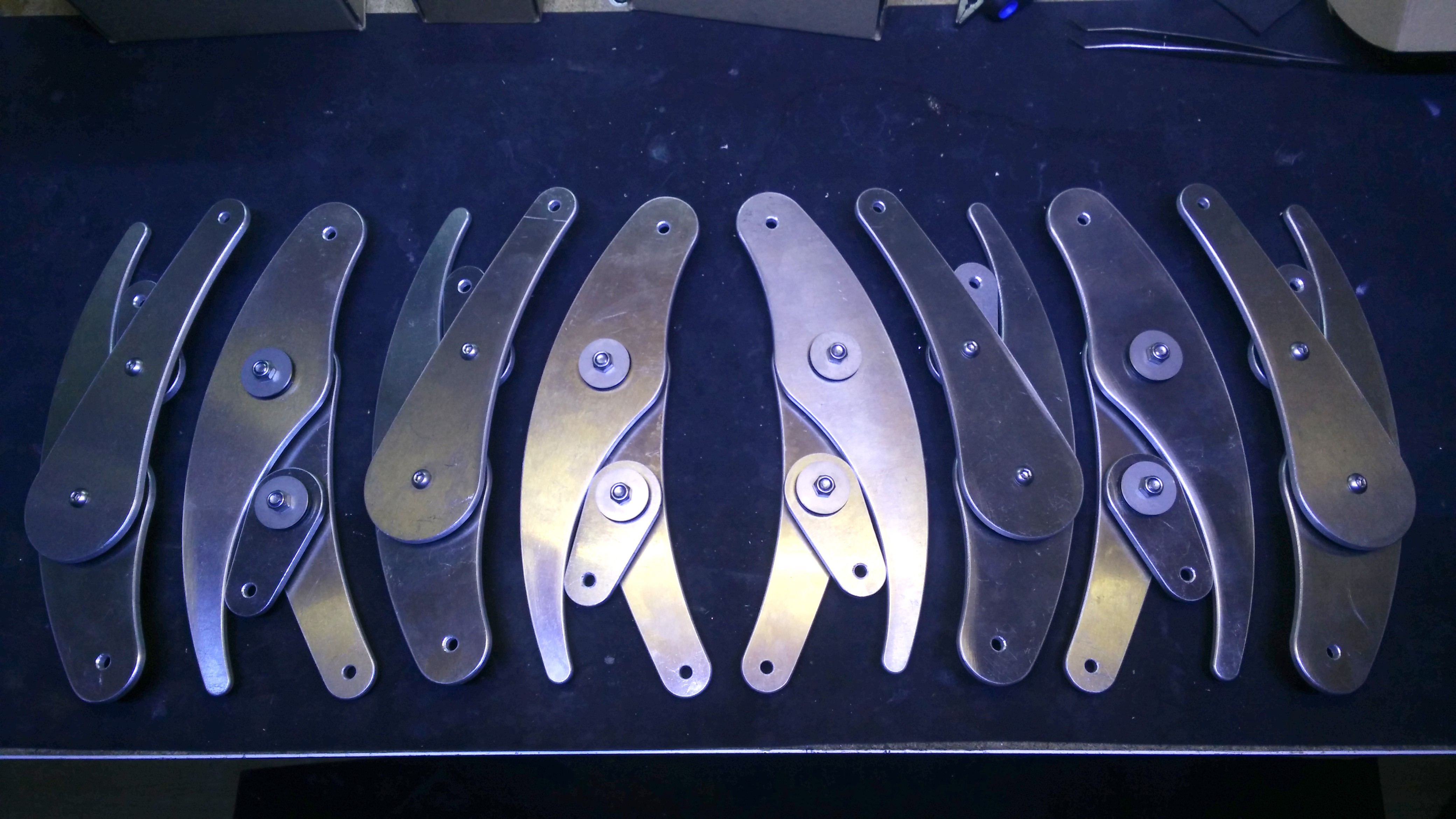
 This are the eight legs assembled, half of them mirrored as they will work in pairs.
 The rest of the joints are built in a similar way.
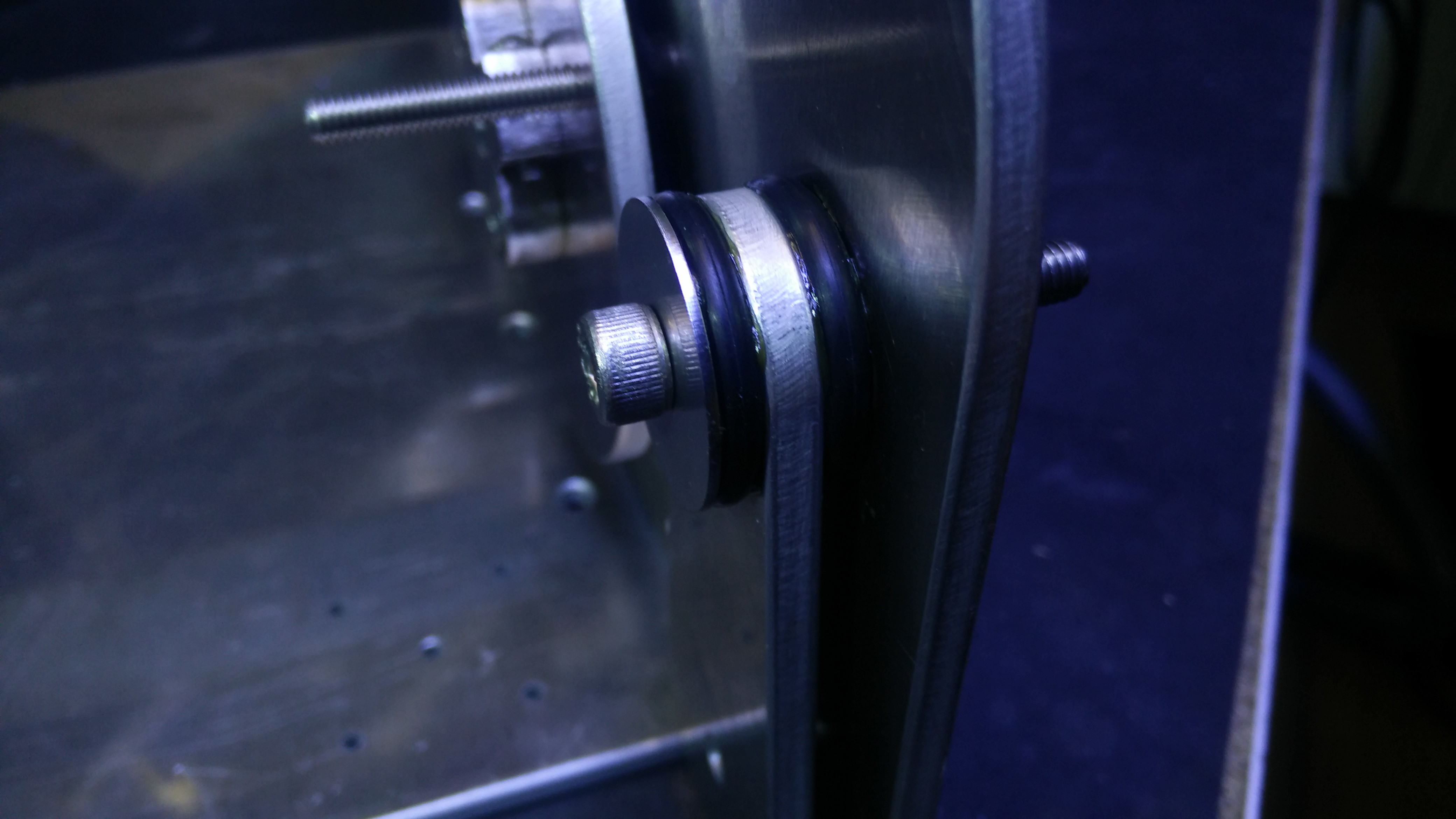
 In this case, for example, the bolt doesn't thread into any part, so a washer and bearing have to be installed before putting it into the first part.
 This are a couple of pivots for the legs, which are attached in pairs to the frame, with the bolt only threaded into the lock nut, otherwise free to rotate.
 The legs are attached to the frame with pivot parts like these, but before fully assembling the leg linkage, i have to install the gear train and get some spacers.
 The geared transmission isn't as simple as the linkage joints, so i will detail its assembly separately.
Discussions
Become a Hackaday.io Member
Create an account to leave a comment. Already have an account? Log In.