 Pinomelean
This log is an explanation of an engineering problem i faced while designing and building the robot. The mechanism shown here won't be part of the finished robot, as it has been a failure.
I decided to include the information anyway so people can understand the design choices i made and the reasons behind them, and hopefully learn something along the way. (Or at least, avoid making similar mistakes)
The octopodal Klann linkage i'm building drives the legs in two groups of four, with a motor for each side. In this way, the mechanism functions in a similar way to a vehicle with two tracks, like a tank.
Each couple of legs in the corners could be powered independently, but that would only complicate the design.
Tying them together in groups of four will ensure there are always four legs on the ground at any given time, two in each side of the robot (at least on a flat surface), making the platform stable and parallel to the ground.
Using this arragement, in each group of four the two external legs are in sync, and 180º apart from the internal ones to ensure that they contact the ground at the same time, and just before the other two lift.
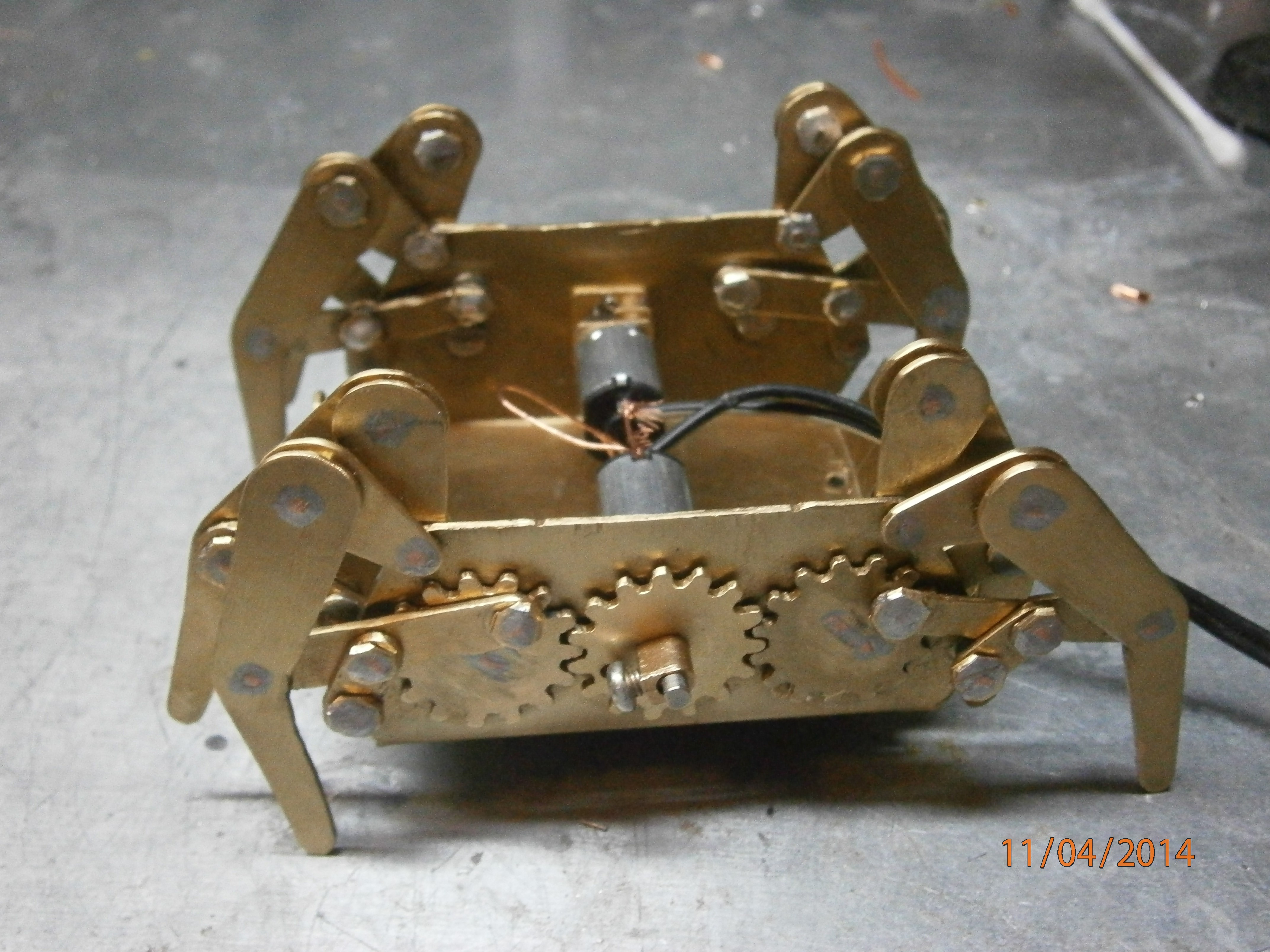
In the brass prototype i powered the outer legs with gears, and those gears drove the internal linkages with a crank through a shaft. The shaft was copper wire soldered to the gear and crank.
As i might have mentioned before, i want the new version to be easily taken apart, for repairs, replacements or improvements. This means i won't join any parts permanently unless it is completely necessary.
The first idea i came up with to tansmit torque from the external gears to the internal linkages was threading the gears and cranks, using threaded rod as the shaft and to tighten lock nuts against the aluminium parts to fix them to the shaft.
I tested the idea on some scrap aluminium and saw that the threads would strip way before applying the torque i expect necessary for this mechanism
The next thing i came up with was fastening a thick stainless disk onto the aluminium parts, the harder steel could be connected to a shaft with a key or a spline.

Standard key and keyways could be used for this, but for some reason i decided to ditch standardized hardware and thought it would be a good idea to make my own coupling.
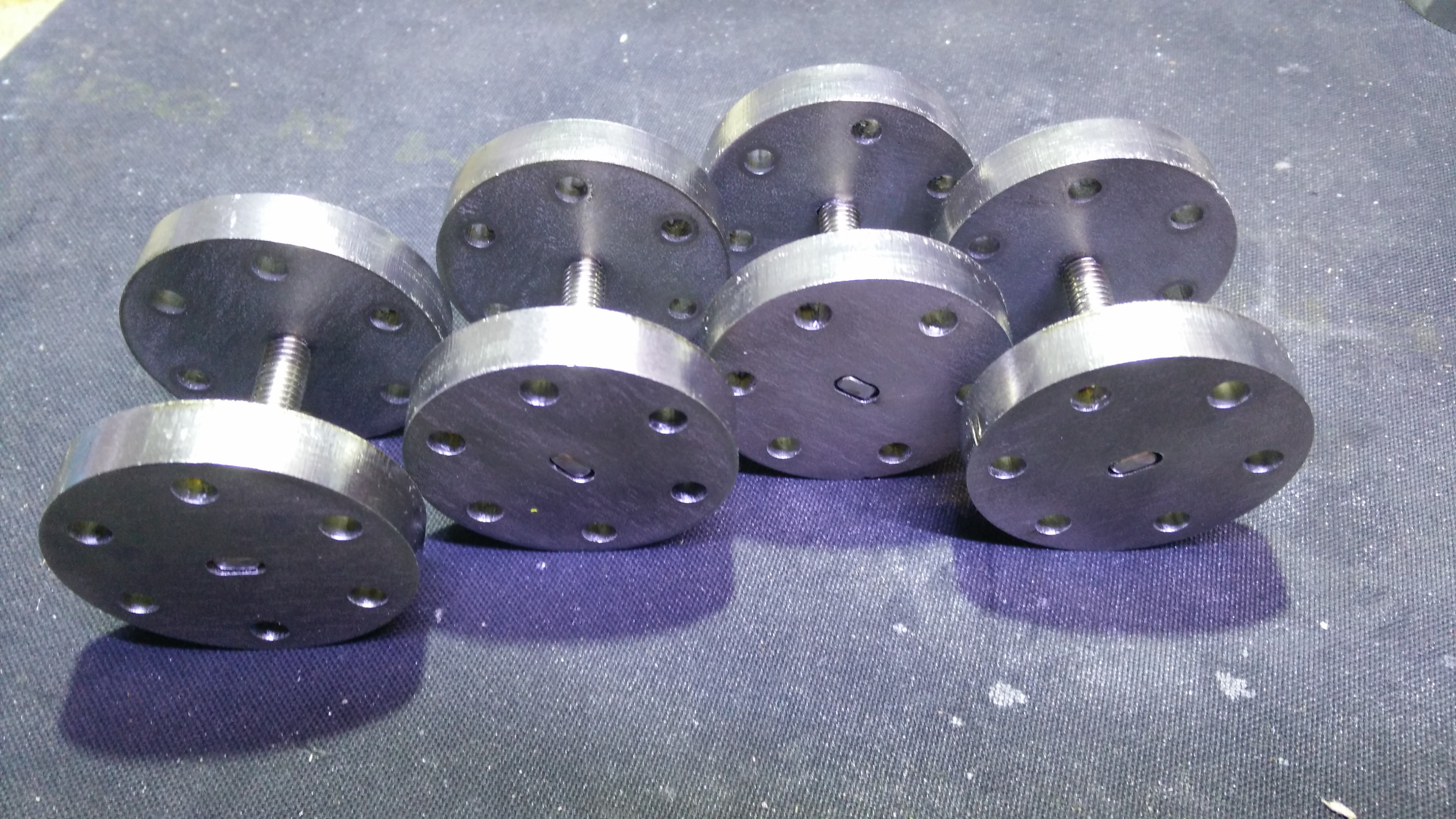
I ordered 8mm stainless discs to be laser cut, with holes in the perimeter to to bolt to the aluminium parts and an oblong hole in the center.
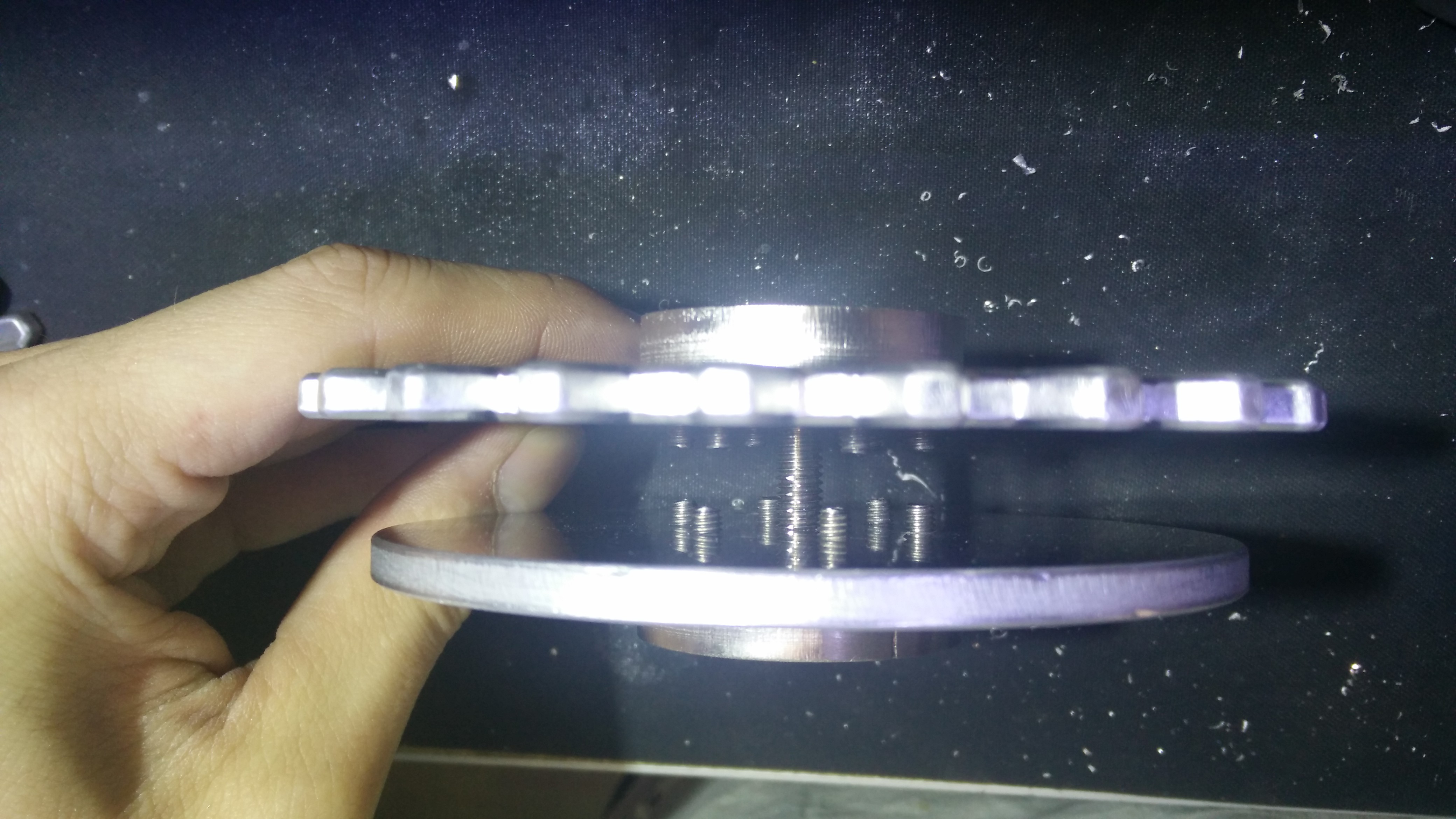
Not wanting to complicate the build process i decided to still use the threaded rod as shafts, i cut the pieces to lenght and ground the ends as flat as i could, aiming for a very tight fit with the discs.
I noticed that some shafts and discs had a little bit of angular backlash, only a little bit, but just enough to feel it. I didn't care much at the time.
Then i countersunk the holes for the screws, and threaded the aluminium parts. (Note that instead of a crank, i use a full wheel for the inner linkages)
I used oversized phillips screws for testing, but later decided to standardize all fasteners to allen socket head screws (all stainless).

I put a pair of them together to test how rigid the setup was, but as i applied torque from the gear to the wheel, the ammount of backlash increased from barely perceptibe, to more than the angle between gear teeth. Which was obviously unacceptable.
While the backlash did grow, it ended settling. This indicated that the coupling appared tight at first only because of the irregular surface left on the laser cut discs. But as torque was applied to the shaft, the surfaces were flattened, creating clearance between the parts.
 While the idea may have seemed good, the tolerances required to make this kind of "splined" joint work well are beyond what can be achieved in the home shop, even with laser cut parts.
I finally scrapped the idea of using threaded rod for the shafts, which rely on tight tolerances to avoid backlash, and the thread itself to keep the parts together.
Since then, i've been designing a solution to transmit torque through the holes in the robot frame, with no backlash between 5mm thin aluminium wheels.
Discussions
Become a Hackaday.io Member
Create an account to leave a comment. Already have an account? Log In.