 Frank Buss
This is a simple RGB fading. It looks like this:
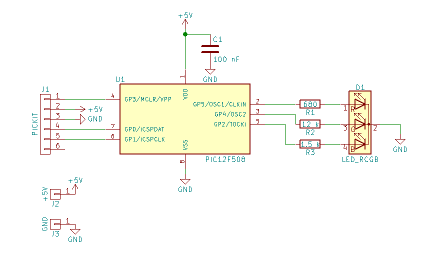
The circuit:
This is the C source code for the XC8 compiler, for MPLAB X:
// simple RGB LED color fading

// PIC12F508 Configuration Bit Settings

// 'C' source line config statements

// CONFIG
#pragma config OSC = IntRC      // Oscillator Selection bits (internal RC oscillator)
#pragma config WDT = OFF        // Watchdog Timer Enable bit (WDT disabled)
#pragma config CP = OFF         // Code Protection bit (Code protection off)
#pragma config MCLRE = OFF      // GP3/MCLR Pin Function Select bit (GP3/MCLR pin function is digital input, MCLR internally tied to VDD)

// #pragma config statements should precede project file includes.
// Use project enums instead of #define for ON and OFF.

#include <xc.h>

#include <stdint.h>

#define RED 0b00100000
#define GREEN 0b00010000
#define BLUE 0b00000100

// global variables need less memory
uint8_t redPwm;
uint8_t greenPwm;
uint8_t bluePwm;
uint8_t out;
uint8_t i;
uint8_t j;
uint8_t k;

void cycle()
{
    // adjust number of cycles for fading speed
    for (k = 0; k < 5; k++) {
        for (i = 0; i < 255; i++) {
            out = 0;
            if (redPwm > i) out |= RED;
            if (greenPwm > i) out |= GREEN;
            if (bluePwm > i) out |= BLUE;
            GPIO = out;
        }
    }
}

int main()
{
    // configure pin 2, 4 and 5 as output
    TRISGPIO = 0b11001011;

    // default value of T0CS overrides the TRIS function, which makes GP2 an
    // input for the timer, disable this to make it an output,
    // and disable all pullups
    OPTION = 0b11000000;

    // fading algorithm
    while (1) {
        // blue to red
        for (j = 0; j < 255; j++) {
            bluePwm = 255 - j;
            redPwm = j;
            cycle();
        }
        cycle();

        // red to green
        for (j = 0; j < 255; j++) {
            redPwm = 255 - j;
            greenPwm = j;
            cycle();
        }
        cycle();

        // green to blue
        for (j = 0; j < 255; j++) {
            greenPwm = 255 - j;
            bluePwm = j;
            cycle();
        }
        cycle();
    }

    return 0;
}
Full project files and KiCAD circuit is in the zip file.


 kodera2t
 Eric Hertz
 dBSound Bracelet
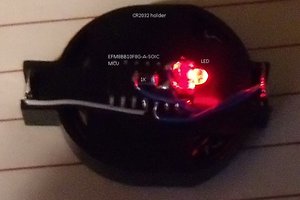
 Jacques
void dither(int x){
Serial.print(" R:");
Serial.print(red);
Serial.print(" G:");
Serial.print(green);
Serial.print(" B:");
Serial.println(blue);
for(int i = 1; i < x; i = i+3){
analogWrite(9, red);
analogWrite(10, green);
analogWrite(11, blue);
delayMicroseconds(i);
analogWrite(9, redOld);
analogWrite(10, greenOld);
analogWrite(11, blueOld);
delayMicroseconds(x-i);
}
analogWrite(9, red);
analogWrite(10, green);
analogWrite(11, blue);
}