Close
0%
0%

Arduino LCD Temperature Controller

Display Temperature on LCD Using an Arduino

Similar projects worth following
I used an analog temperature sensor connected to an Arduino UNO R3 to measure the temperature and then display the results on an LCD screen.

We build off of using the LCD display and add a temperature sensor that will use the ADC on the Arduino to read and display the room temperature.

LCD Modules and LCD Driver Chips

Most LCD displays that you can purchase are actually a module: it contains an LCD display driver chip (usually the Hitachi HD44780 or some variant) along with the other necessary circuitry to make the display work. Over at SparkFun you can find a datasheet for a LCD Module and a LCD Driver chip.

lcd arduino

In the diagram above for the LCD driver chip you can see there is a MPU Interface where you connect a microcontroller to drive the LCD driver chip. The LCD is a parallel interface so the LCD driver chip has to interface to the actual LCD display.

lcd arduino

Looking at the LCD Module block diagram you get a better understanding of how the LCD driver chip and the actual LCD display are connected together. By using a module all of the connections and the extra circuitry to connect the LCD driver chip to the display are already done for you. Now you can see that you will interface the Arduino to the LCD driver chip on the module along with some extra pins for the backlight display and the rest is taken care of for you.
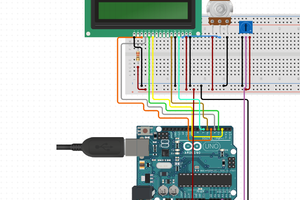
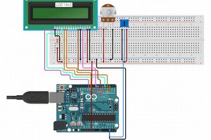
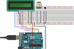
Hardware Setup

lcd arduino

Most LCD modules will have a 16 pin configuration.

Vo => Constrast Adjust. You will need to connect a 10K pot to this pin in order to change the contrast.

RS => Register Select. Controls where in LCD memory you are writing to which can be data register or instruction register.

R/W => Read/Write. Select read or write mode.Write mode is "0" so often times you will see this pin connected to ground rather than use up an IO pin on the microcontroller.

E => Enable. Enable for read or write mode.

LED+/LED- => Backlight Pins.Connect to power and ground in order to provide backlight to the LCD display.

lcd arduino

Analog Devices TMP36 Temperature Sensor

The TMP36 is an integrated circuit from Analog Devices that provides an output voltage that is linearly proportional to the temperature in Celsius. It can measure the temperature from -40C to +125C with a resolution of 10mV/C degree and can be powered from a 2.7V to 5.5V supply. The output voltage is 750mV at 25C with an offset voltage of 500mV to account for negative temperatures.

lcd arduino

Since the TMP36 outputs an analog voltage you will use the built-in Analog-to-Digital Converter (ADC) of the Arduino. The TMP36 is a 3 lead device and has 3 pins: VCC, GND, and VOUT where you will connect VOUT to one of the analog input pins of the Arduino Uno.

lcd arduino

Looking at the graph above you can see the linear relationship between the sensor output voltage and temperature which makes writing the code to figure out the temperature pretty easy to do.

Using the ADC

In order to use the ADC properly we first need to understand how it works. An ADC will take an analog voltage and then convert it to a digital value by continually sampling the signal. The accuracy of an ADC depends on the resolution. The Arduino Uno has a 10bit ADC so that means you can subdivide or quantize the signal into 2^10 values or 1024 values. So when you read an analog voltage from a sensor it will translate the voltage on a scale from 0 to 1023 where the upper limit (5V in Arduino case) will be 1023.

To get better accuracy you can use the external reference voltage for your ADC measurements. By default the Arduino Uno uses the 5V internal power supply for the ADC reference voltage. This is fine if your sensor outputs voltage values up to 5V but what if it doesn't? For example the TMP36 outputs 750mV at 25C but the Arduino is still using 5V as the 100% voltage range. The step size returned from reading the ADC on the Arduino is 1024/5V giving a step size of 4.88mV. Instead you can apply a lower voltage the AREF pin which will result in a smaller step size and better overall accuracy of your sensor. Different Arduino boards have internal and external references that you can use and it's best to consult the Arduino website and look...

Read more »

sketch_temp_controller.ino

Arudino file for temperature sensor with LCD display

ino - 2.69 kB - 06/30/2017 at 03:18

Download

  • 1 × Arduino UNO R3 microcontroller
  • 1 × TMP36 Sensors / Temperature, Thermal
  • 1 × Hitachi HD44780 LCD display

  • Using Analog Temp Sensor with LCD on Arduino

    Timothy Coyle06/30/2017 at 03:20 0 comments

    Hardware Setup

    In this example I hook up the TMP36 sensor to one of the analog input pins on the Arduino Uno and then I tie the 3.3V output supply from the Arduino to the AREF pin using it as an external reference for the ADC to get better accuracy. (When I used the default 5V supply for reference I did notice a bigger temperature difference by about 6 degrees compared to using the external reference) I am also using the LCD from a previous example to display the measured temperature.

    lcd arduino

    Temperature Sensor Sketch

    For the code you need to read the analog input pin and then convert the value to voltage from the ADC. Then you need to convert the voltage to the temperature based on the TMP36 datasheet.

    Below is the Sketch to read the temperature sensor and display result to LCD:

    //
    //Date: 8/14/15
    //Version: 1.0
    //
    //Comments:
    //This sketch reads an analog temperature sensor and writes the temperature in F to the LCD display. 
    //
    // LCD Pinout Connection:
    // RS Pin: Connect to digital input 2.
    // Enable Pin: Connect to digital input 3.
    // D4 Pin: Connect to digital input pin 4.
    // D5 Pin: Connect to digital input pin 5.
    // D6 Pin: Connect to digital input pin 6.
    // D7 Pin: Connect to digital input pin 7.
    // R/W Pin: Connect to Ground so in write mode which is logic low "0".
    // Vo Pin: Connect to the 10K pot that is connected between power and ground.
    //
    // Analog Temperature Sensor Connection:
    // Vout Pin: Connect to analog input 0.
    //
    
    // Arduino LCD Display Library
    #include 
    
    // Call the library with the right pin configuration
    // In this sketch we are using: lcd(RS,EN,D4,D5,D6,D7) in 4 bit mode
    LiquidCrystal lcd(2,3,4,5,6,7);
    
    // The AREF pin is tied to the 3.3V output pin to be used as an external reference for the ADC
    #define aref_ext_voltage 3.3
    
    // Assign Arduino analog input pin to be connected to temp sensor 
    int tempPin = 0;        
    
    // Assign a variable to hold the temperature sensor reading                        
    int tempVal;        // the analog reading from the sensor
    
    // The setup runs once when you press reset or power on the board
    void setup() {
      // Setup the LCD display column and row
      // We are using a 20x4 display in this example
      lcd.begin(20, 4);
        
      // Need to tell Arduino that we are using an external voltage reference for ADC
      // Always have to set this first before calling analogRead() or else you could short out your board
      analogReference(EXTERNAL);
      // Allow voltage on ADC to settle out before reading
      analogRead(0);
     
    }
    
    void loop() {
    
      // Read the temperature sensor and store the value
      tempVal = analogRead(tempPin);  
     
      // Convert the digitized number 0-1023 from the ADC into a voltage based on the reference voltage
      // For an external reference voltage of 3.3V => (ADC value) * (3.3V/1024)
      float voltageConvert = tempVal * aref_ext_voltage;
      voltageConvert /= 1024.0; 
     
      // Convert the voltage into temperature using the linear graph data from the TMP36 datasheet
      // TMP36 has 500mV offset and 10mV/C degree scale
      // Temp in C = (Voltage - 500mV)/10
      // Voltage is in Volts so multiply by 100 instead of divide by 10 to get correct result (1000mV=1V)
      float tempC = (voltageConvert - 0.5) * 100 ;  
                                                   
      // Convert C to F
      float tempF = (tempC * 9.0 / 5.0) + 32.0;
      
      // Print a message to the LCD.
      lcd.setCursor(0, 0);  // set the start of the message to be first column first row
      lcd.print("The current temp is ");
      lcd.print(tempF);
      lcd.print(" degrees F");
    
    }
                                

    The temperature sensor was reading around 73 F and my room thermostat was showing 71 F so for a basic thermostat this would work fine.

  • Connecting LCD to Arduino

    Timothy Coyle06/30/2017 at 03:17 0 comments

    How I connected and programmed the LCD to Arduino Uno R3:

    lcd arduino

    As you can see from the picture above it can be a little messy to connect up the LCD module to the Arduino Uno board. I usually try to keep my wire colors coordinated so I know what are power, ground, and data but didn't have everything I needed this time around. Below is the circuit diagram which is easier to look at:

    lcd arduino

    LCD Sketch

    The LCD module that I used was a 20x4 which means 20 characters per row and 4 rows. To display a message on the LCD display you need to put the message into the LCD display registers then put instructions in the LCD instruction register. This can be a little complicated but the Arduino has a built-in library to handle the low level interaction for you. The key is to use the right setup with the LiquidCrystal() function as described below from the Arduino website:

    lcd arduino

    Below is the Sketch for the Arduino Uno to send a message to the LCD:

    //
    //Date: 8/2/15
    //Version: 1.0
    //
    //Comments:
    //This sketch writes a message to a 20x4 character LCD display. 
    //
    // LCD Pinout Connection:
    // RS Pin: Connect to digital input 2.
    // Enable Pin: Connect to digital input 3.
    // D4 Pin: Connect to digital input pin 4.
    // D5 Pin: Connect to digital input pin 5.
    // D6 Pin: Connect to digital input pin 6.
    // D7 Pin: Connect to digital input pin 7.
    // R/W Pin: Connect to Ground so in write mode which is logic low "0".
    // Vo Pin: Connect to the 10K pot that is connected between power and ground.
    // Arduino LCD Display Library
    #include 
    
    // Call the library with the right pin configuration
    // In this sketch we are using: lcd(RS,EN,D4,D5,D6,D7) in 4 bit mode
    LiquidCrystal lcd(2,3,4,5,6,7);
    
    // The setup runs once when you press reset or power on the board
    void setup() {
      // Setup the LCD display column and row
      // We are using a 20x4 display in this example
      lcd.begin(20, 4);
     
    }
    
    // Main code for Arduino goes in the loop function to be run over and over again
    void loop() {
      lcd.setCursor(0, 0);  // set the start of the message to be first column first row
      lcd.print("Line 1");  // print a message to the LCD  
      lcd.setCursor(0, 1);  // set the cursor to print beginning of second line
      lcd.print("Line 2");  // print a message to the LCD
      lcd.setCursor(0,2);   // set the cursor to print beginning of third line
      lcd.print("Line 3");  // print a message to the LCD
      lcd.setCursor(0,3);   // set the cursor to print beginning of fourth line
      lcd.print("Line 4");  // print a message to the LCD
    }


View all 2 project logs

Enjoy this project?

Share

Discussions

Similar Projects

Does this project spark your interest?

Become a member to follow this project and never miss any updates