 Timothy Coyle
One of the sensors I'll be using in the connected pool monitor is an analog sensor (Analog Devices TMP36) to read the air temperature and display to the user.
Analog Devices TMP36 Temperature Sensor
The TMP36 is an integrated circuit from Analog Devices (datasheet here)that provides an output voltage that is linearly proportional to the temperature in Celcius. It can measure the temperature from -40C to +125C with a resolution of 10mV/C degree and can be powered from a 2.7V to 5.5V supply. The output voltage is 750mV at 25C with an offset voltage of 500mV to account for negative temperatures.

Since the TMP36 outputs an analog voltage you will use the built-in Analog-to-Digital Converter (ADC) of the Arduino. The TMP36 is a 3 lead device and has 3 pins: VCC, GND, and VOUT where you will connect VOUT to one of the analog input pins of the Arduino Uno.

Looking at the graph above you can see the linear relationship between the sensor output voltage and temperature which makes writing the code to figure out the temperature pretty easy to do.
Using the ADC
In order to use the ADC properly we first need to understand how it works. An ADC will take an analog voltage and then convert it to a digital value by continually sampling the signal. The accuracy of an ADC depends on the resolution. The Arduino Uno has a 10bit ADC so that means you can subdivide or quantasize the signal into 2^10 values or 1024 values. So when you read an analog voltage from a sensor it will translate the voltage on a scale from 0 to 1023 where the upper limit (5V in Arduino case) will be 1023.
To get better accuracy you can use the external reference voltage for your ADC measurements. By default the Arduino Uno uses the 5V internal power supply for the ADC reference voltage. This is fine if your sensor outputs voltage values up to 5V but what if it doesn't? For example the TMP36 outputs 750mV at 25C but the Arduino is still using 5V as the 100% voltage range. The step size returned from reading the ADC on the Arduino is 1024/5V giving a step size of 4.88mV. Instead you can apply a lower voltage the AREF pin which will result in a smaller step size and better overall accuracy of your sensor. Different Arduino boards have internal and external references that you can use and it's best to consult the Arduino website and look at the examples.
Hardware Setup
In this example I hook up the TMP36 sensor to one of the analog input pins on the Arduino Uno and then I tie the 3.3V output supply from the Arduino to the AREF pin using it as an external reference for the ADC to get better accuracy. (When I used the default 5V supply for reference I did notice a bigger temperature difference by about 6 degrees compared to using the external reference) I am also using the LCD from a previous example to display the measured temperature.

Temperature Sensor Sketch
For the code you need to read the analog input pin and then convert the value to voltage from the ADC. Then you need to convert the voltage to the temperature based on the TMP36 datasheet.
The sketch below reads an analog pin connected to the sensor and displays the result to the serial monitor.
//
//Date: 6/16/17
//Version: 1.0
//
//Comments:
//This sketch reads an analog temperature sensor and writes the temperature in F to the serial monitor
//
// Analog Temperature Sensor Connection:
// Vout Pin: Connect to analog input 0.
//
// The AREF pin is tied to the 3.3V output pin to be used as an external reference for the ADC
#define aref_ext_voltage 3.3
// Assign Arduino analog input pin to be connected to temp sensor
int tempPin = 0;
// Assign a variable to hold the temperature sensor reading
int tempVal; // the analog reading from the sensor
// The setup runs once when you press reset or power on the board
void setup() {
// We'll send debugging information via the Serial monitor
Serial.begin(9600);
// Need to tell Arduino that we are using an external voltage reference for ADC
// Always have to set this first before calling analogRead() or else you could short out your board
analogReference(EXTERNAL);
// Allow voltage on ADC to settle out before reading
analogRead(0);
}
void loop() {
// Read the temperature sensor and store the value
tempVal = analogRead(tempPin);
// debug - print raw along reading to serial monitor
//Serial.print(tempReading);
// Convert the digitized number 0-1023 from the ADC into a voltage based on the reference voltage
// For an external reference voltage of 3.3V => (ADC value) * (3.3V/1024)
float voltageConvert = tempVal * aref_ext_voltage;
voltageConvert /= 1024.0;
// debug - print out the voltage
//Serial.print(" - ");
//Serial.print(voltageConvert); Serial.println(" volts");
// Convert the voltage into temperature using the linear graph data from the TMP36 datasheet
// TMP36 has 500mV offset and 10mV/C degree scale
// Temp in C = (Voltage - 500mV)/10
// Voltage is in Volts so multiply by 100 instead of divide by 10 to get correct result (1000mV=1V)
float tempC = (voltageConvert - 0.5) * 100 ;
// Convert C to F
float tempF = (tempC * 9.0 / 5.0) + 32.0;
// Print temperature in F to serial monitor
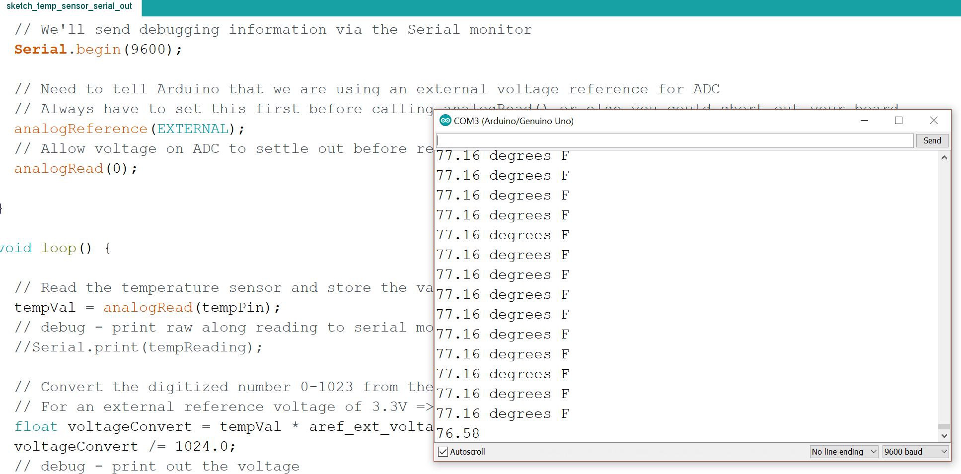
Serial.print(tempF); Serial.println(" degrees F");
}
Here's a screenshot of it running:
Discussions
Become a Hackaday.io Member
Create an account to leave a comment. Already have an account? Log In.