Ryan Logsdon
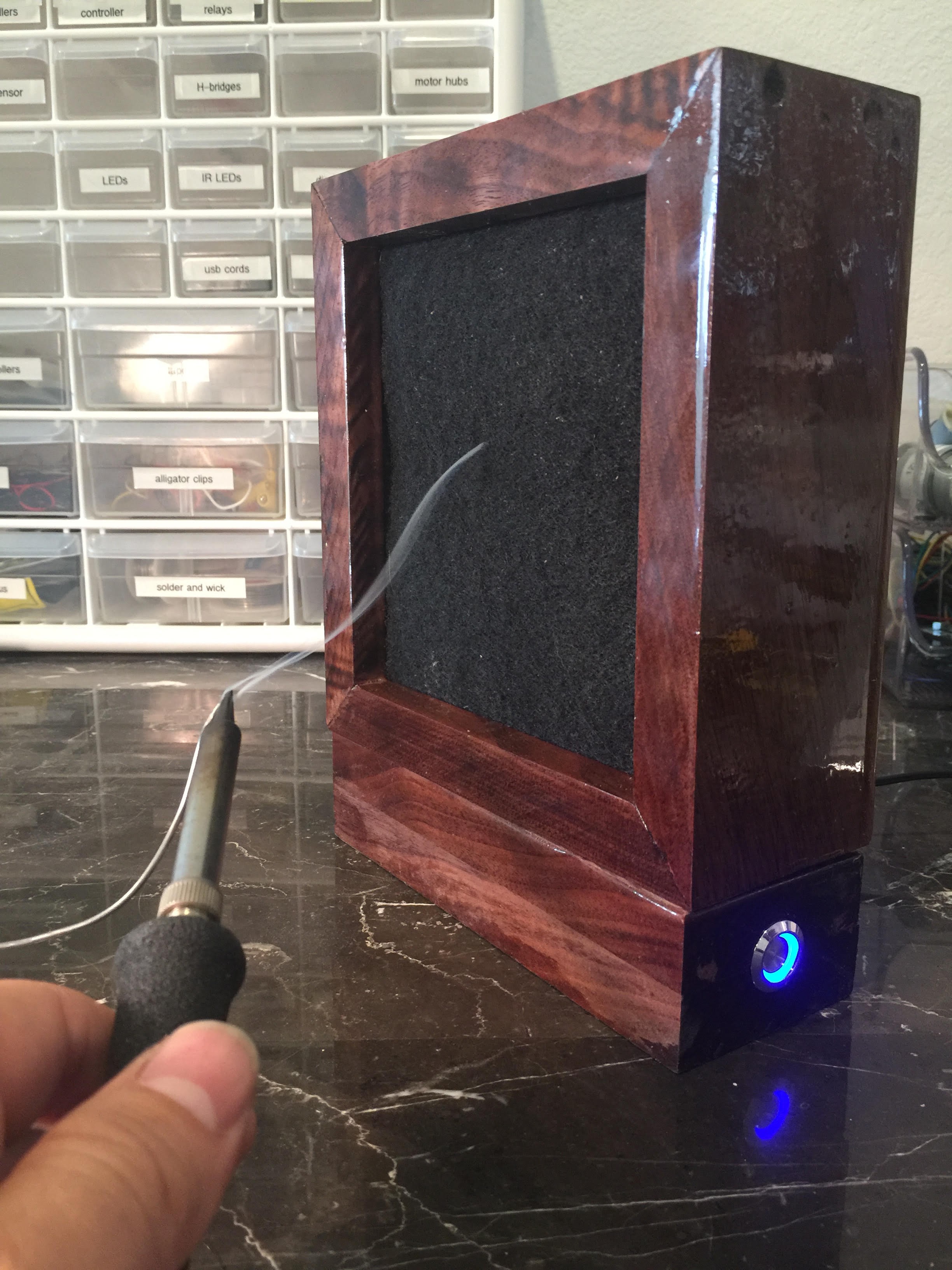
Finished Product
This is what we'll be building...
Materials List
- 140mm computer fan ($7.99, Cooler Master)
- latching push-button ($9.99, Yakamoz)
- female power-jack adaptor ($6.99, generic plug)
- 12 volt power supply ($7.99, generic power supply)
- 4 feet of 0.75" x 2.5" walnut wood ($3.85/ft, Home Depot)
- carbon filter pad ($7.99, generic filter)
- super glue (2 cents worth)
- 400-grit sand paper (3 cents worth)
Tools List
- saw
- hand router (Ryobi Trim Router)
- epoxy (Tap Plastics: A-Side Resin 314 and B-Side Hardener 102)
- finishing nail gun (Ryobi Brad Nailer)
Cost: $45 (under budget!)
Overview
The project has two main parts: (1) building the wooden frame and (2) managing the wires we'll be storing away in the frame. I'll explain the wire connections in detail, and let the pictures do most of the talking when building the frame. Let's begin!
Frame
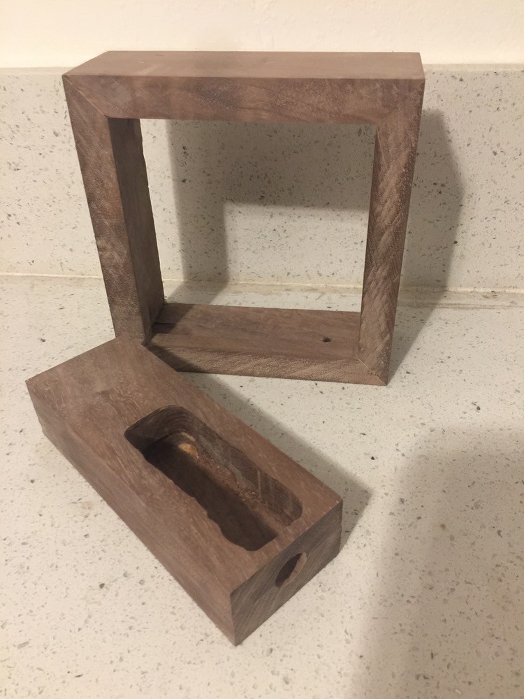
1. I don't have access to a CNC router, so I used a hand router to cut to a depth of 6mm, removing all but the front 13mm of wood. This creates a lip that our fan will be pressed up against from the inside of the frame. Cut the wood into lengths of 170mm at the longest part. 45 degree angles to make a frame shape.
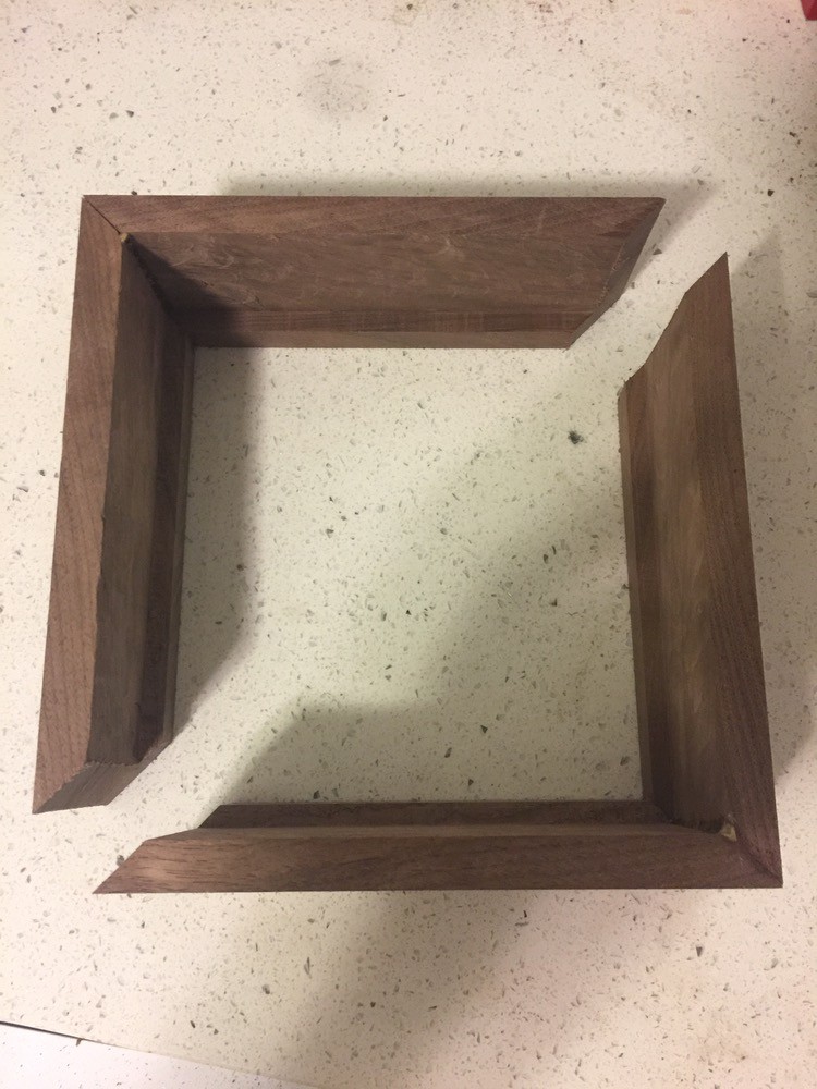
2. Glue the parts together, wait 30 minutes until stable, then sink a few brad nails (slim nails without the customary flat heads) into the corners.
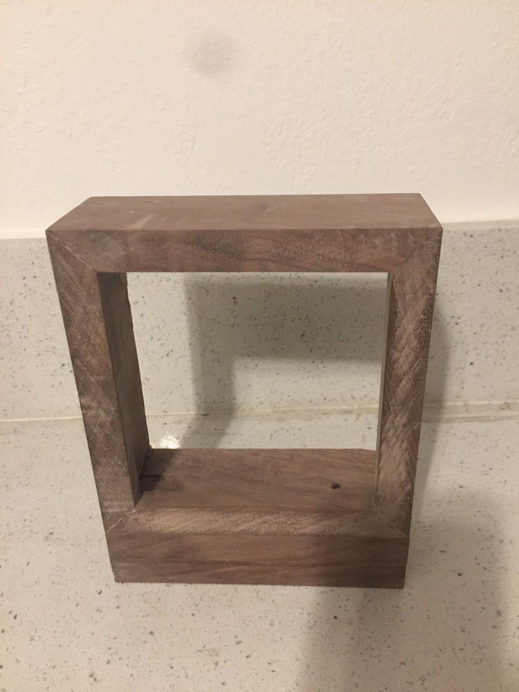
3. Cut 2 more pieces of wood at 170mm lengths, this time at 90 degrees. This will provide us our base. Glue these 2 pieces on top of one another. Wait until it drys - about 30 minutes for Elmer's Wood Glue. Here's what it looks like stacking the frame onto the base (don't glue the frame to the base just yet!)...
4. Using the hand router again, we need to create 3 holes.
- a hole on the right side for the push button to slip into
- a hole on the back for the female power plug to sink into
- a large cavity to store the body of the push-button and all wires
Then using a drill, make a small hole in the bottom of the frame to pass the fan's wires down to our large cavity in the base.
(not shown: hole in the back for power)
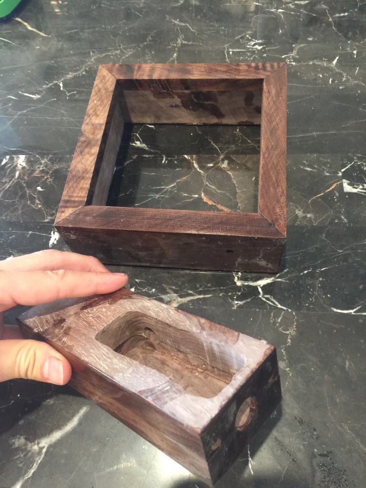
5. Epoxy time! I use Tap Plastics for my wood projects. See the link above to their site for full instructions. Don't coat the bottom of the frame and the top of the base (we need them flat and flush later). And don't worry about coating all at once. As you can see, I didn't epoxy the inside walls of the frame on my 1st pass.
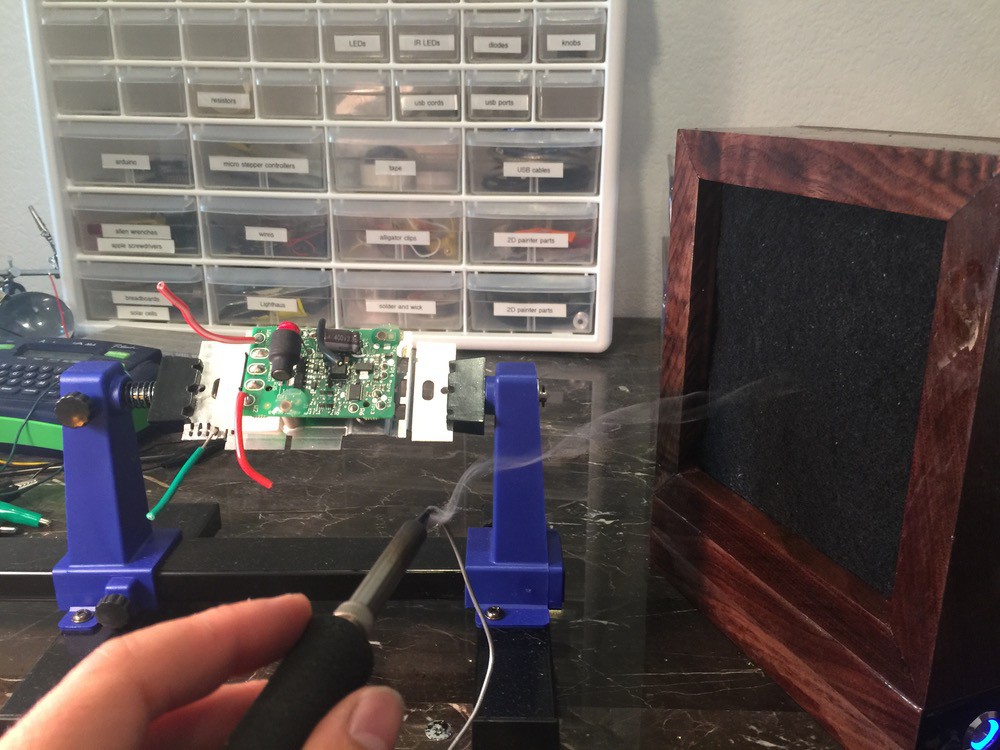
Wire Management
Finally, it's time to put the guts of our project together!
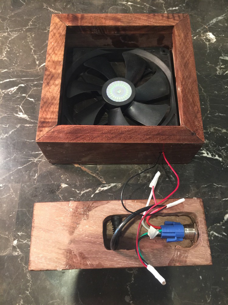
1. Mount the power cord and the push button into the base. Trim a LOT of that power cord off.
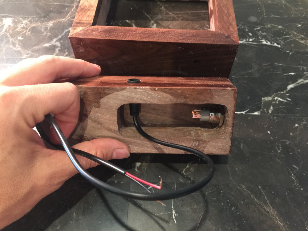
2. Attach the wired end cap that came with the push button. It looks like this blue piece...
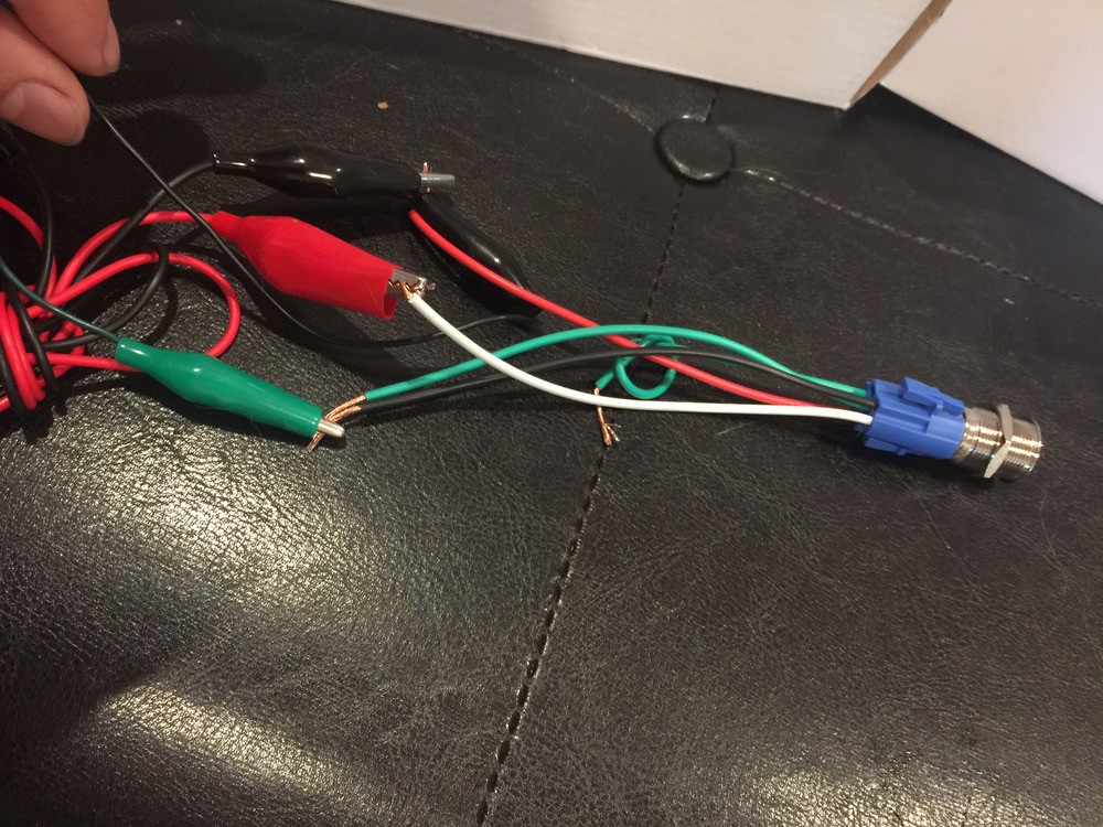
3. Let's orient ourselves the same way, looking at the push button's end-cap of colored wires. There is a green wire on top, a middle row of red, then green, then black wires, and a bottom white wire. For the schematic, see this. We'll follow option 1, but the lettering is too faint on the actual device, so orient yourself by the colors...
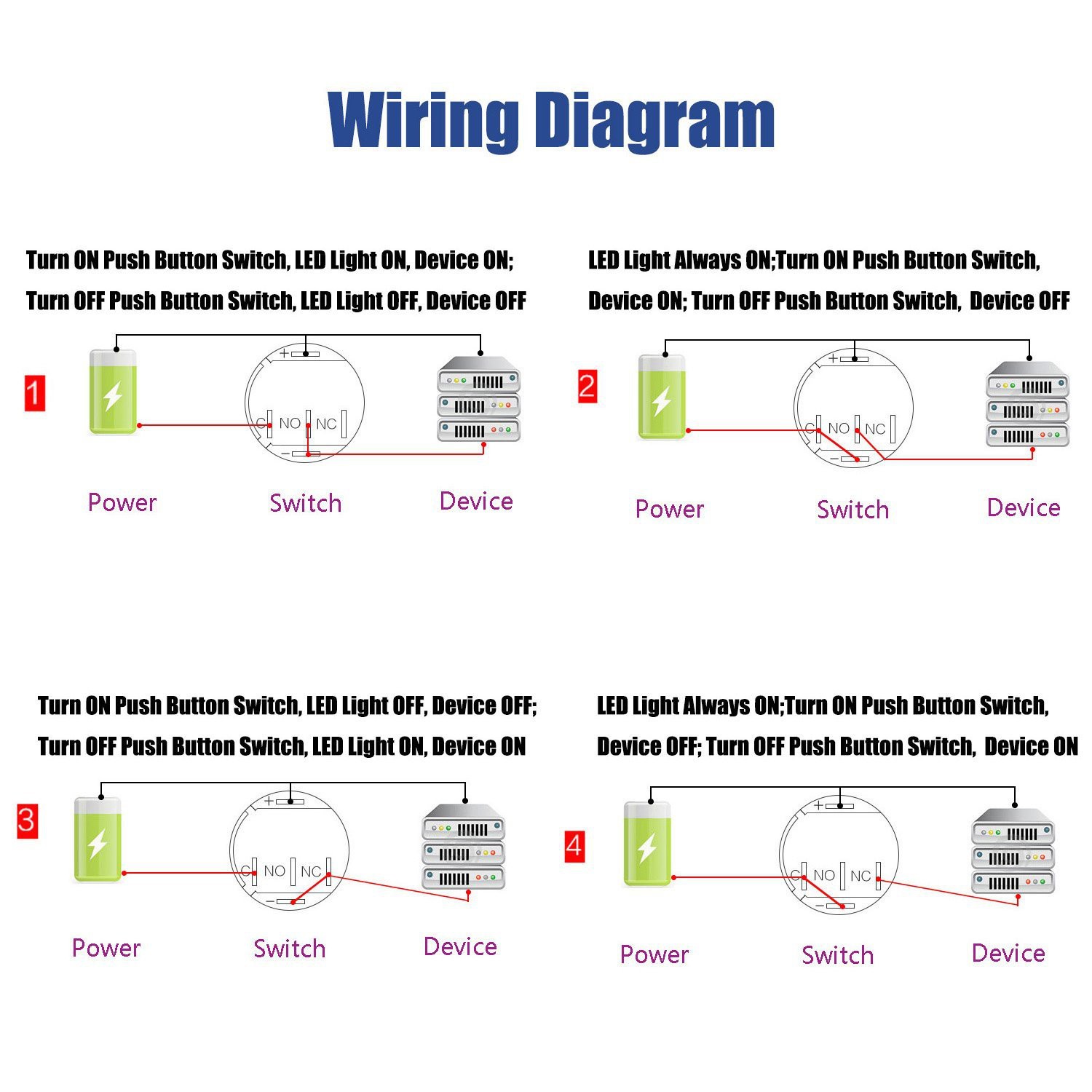
4. The top, green wire is not used, so either tie it off or cut it off and tape the end.
5. Next we'll work on the center line of wires...
Red: this is the ground wire. Solder this to the ground wire (black) of your fan as well as the ground wire (also black) of your power adaptor. Make sure to snake your fan's wires through the frame's hole!
Green and Black: solder these 2 wires together, and solder them to the power (red) of your fan.
6. The bottom, white wire is input power. Solder it to the power (red) of your female power adaptor.
7. Run tape over the soldered ends and tuck your wires into the cavity.
Finishing Steps
Cut out a square of the carbon filter a few cm larger than the fan, itself. Place the filter in front of the fan, and gently push both in place. That's it! It'll be held in with tension alone!
Need to replace the filter? Just push the fan gently, and you have full access.
To seat the base and frame together, use the nail gun once more. Then do a 2nd pass with epoxy. If there are any raised bumps in your epoxy or other imperfections, you can sand them out, dust those spots off, and add more epoxy. You won't be able to tell that there was ever a problem.
Happy soldering!
- Ryan