 Roald Lemmens
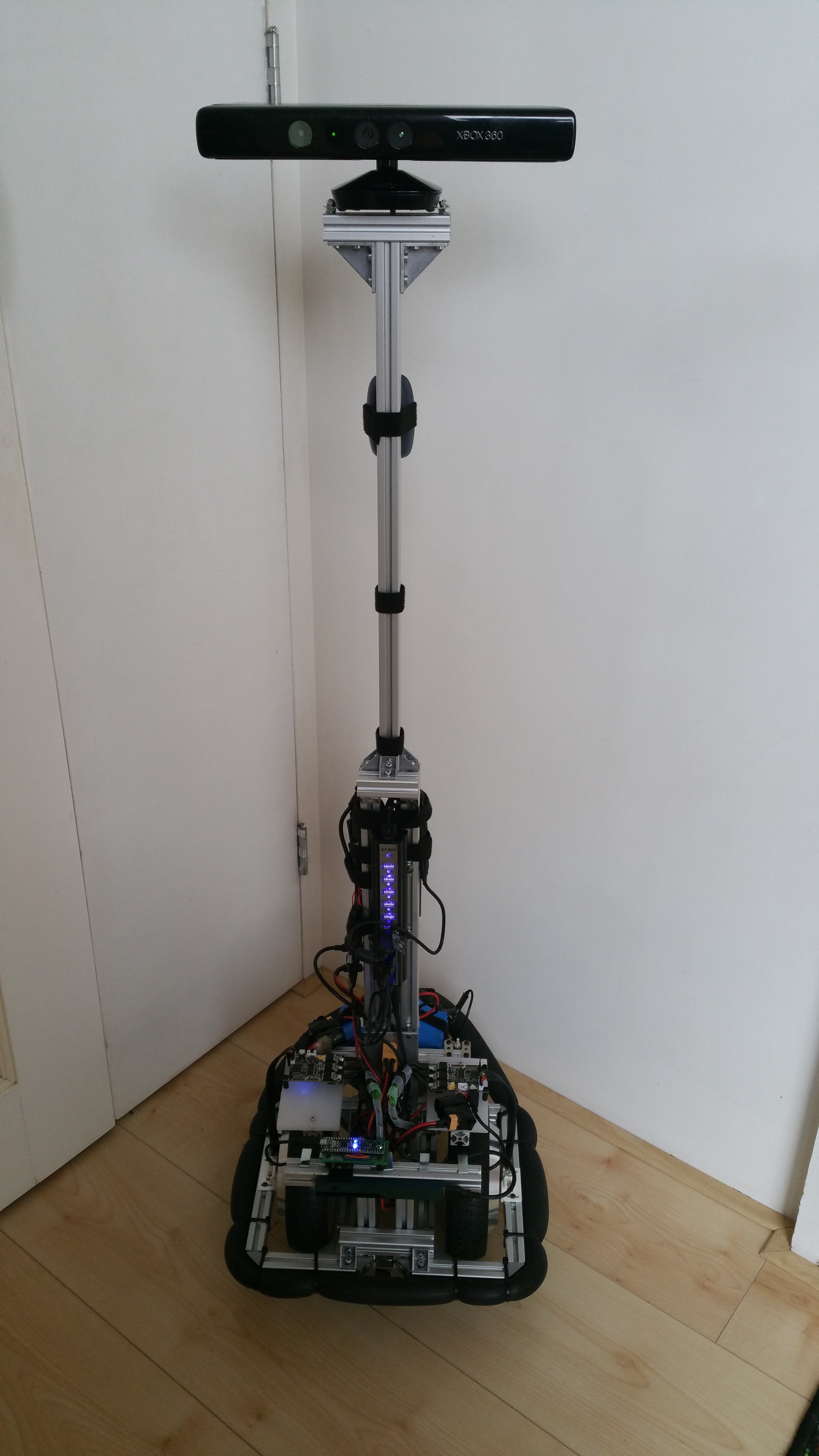
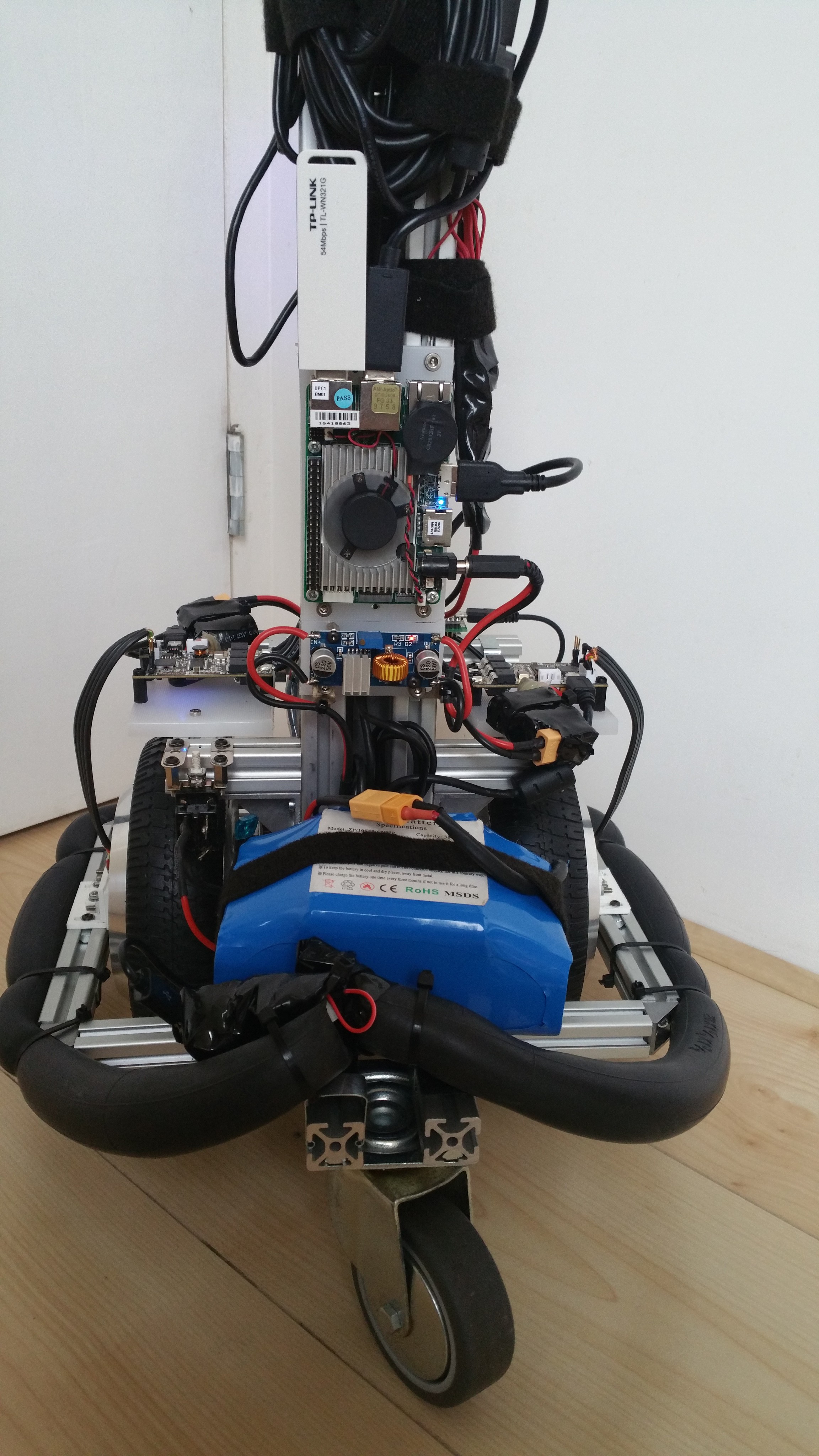
With good results from the encoder it was time to address some of the issues and do another (you guessed it) redesign. Let me start by showing the result first, for a change. I will go into the details after the break.
Frame design
While the initial results of the encoder were very promising, the mounting of the sensor was a bit fragile. A small bump would move the sensor out-of-range resulting in the wheel no longer being controllable. Since I also wanted the frame to be even more smaller I redesigned the frame to have the wheels as close to each other as possible and have a beam enclose each wheel to allow the mounting of the encoder board with protection.
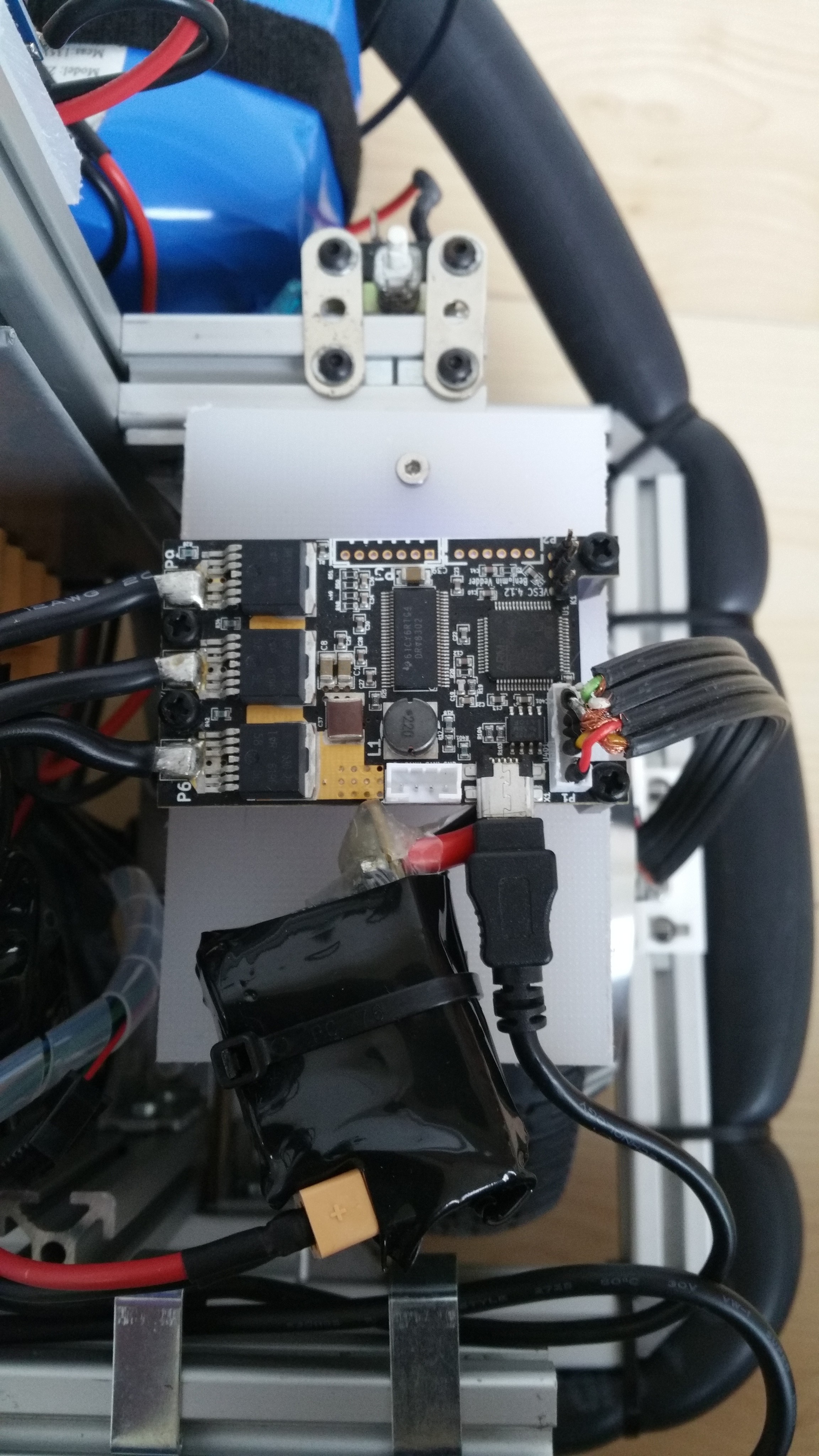
Before I mounted the (heat shrinked) VESC's using some Velcro straps, but now they needed to be mounted more securely, because of the added cable for the encoder. So I mounted them on a piece of 8mm polyethylene. Because the mounting holes are somewhat dangerously close to the power connections, I used plastic standoffs and bolts to mount them. Since I didn't have the right connector at the time, the sensor cable is soldered directly on the connector.
Computer
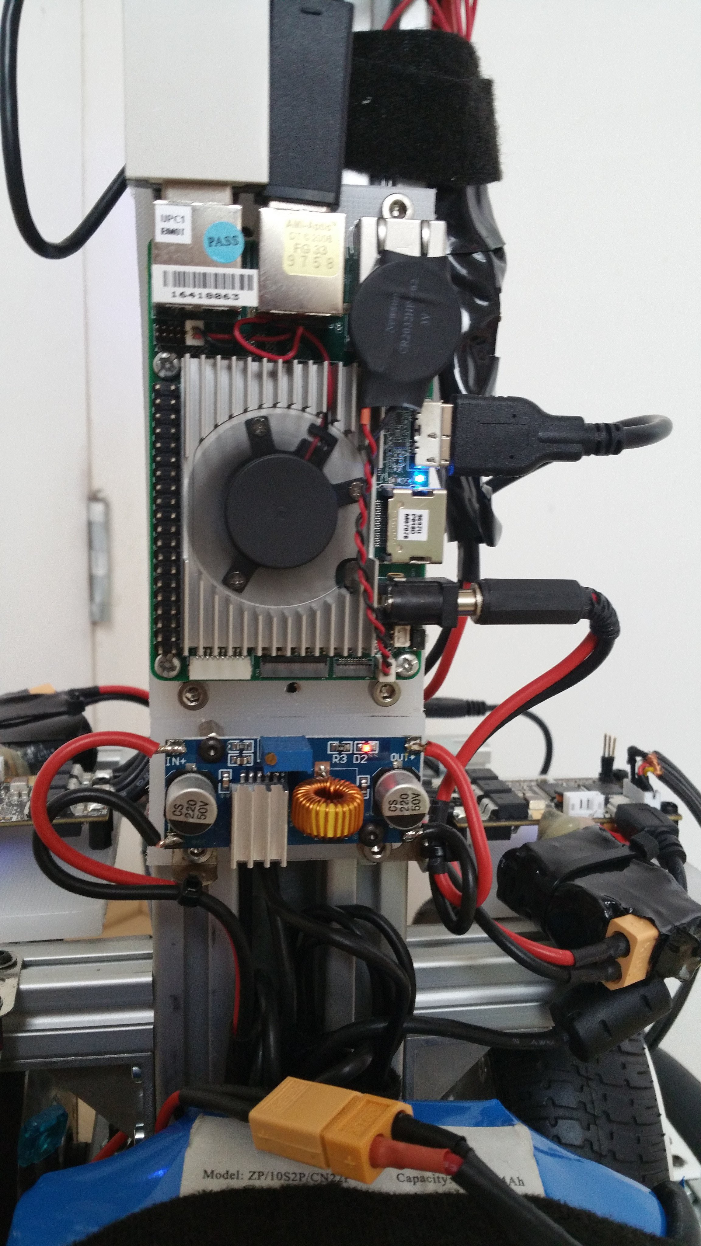
I had ordered a Intel Robotics Developer kit with a RealSense R200 earlier with the idea to have it run the basic navigation and driving of the mobile base. It could be complemented by a faster computer (on- or off-robot) for additional processing later. The robotics developer kit comes with an UP (first generation) board, a Raspberry PI sized computer with an Intel x5-Z8350 Atom quad core processor with USB3 (for the RealSense camera). Main benefit being the smaller size and weight, while still have enough performance to run the navigation stack and even visual odometry. I like the small size of the RealSense camera, which allows it to be mounted lower and keep the base compact. For now I ditched the idea of having a screen thinking this could be added later if needed. But the introduction of the UP board required me to change the power supply. The UP board is powered by an XL4015 DC-DC converter and required another power connection.
Power supply and soft start
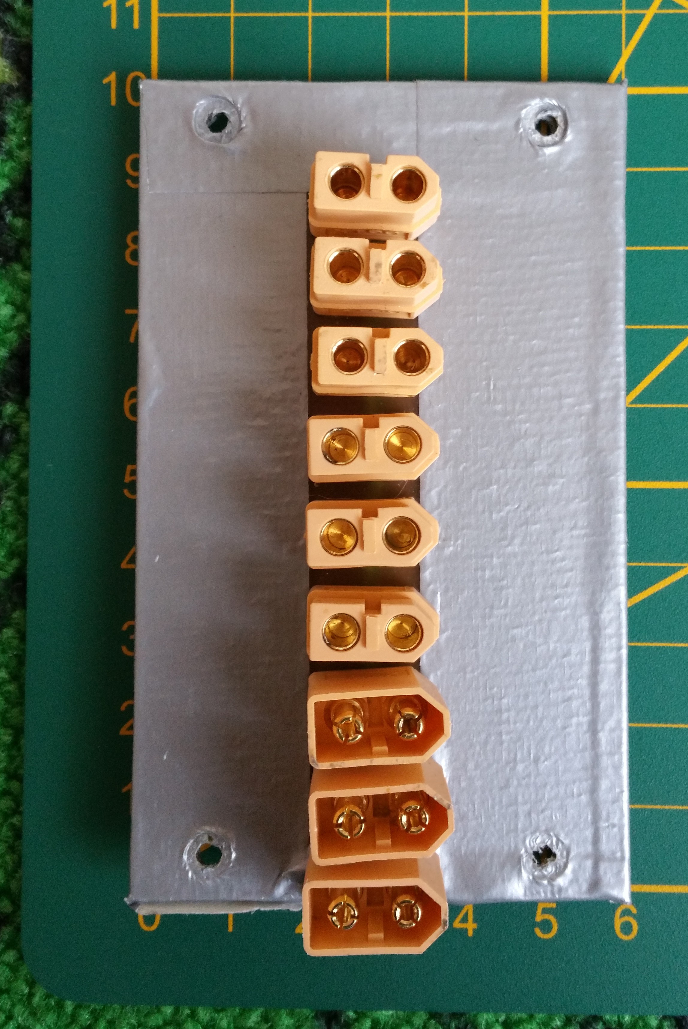
Before I created a power supply splitter cable with 1 in 3 out XT-60 connectors to power both VESC's and one additional DC-DC converter for the Kinect sensor. This had already shown its limitations as I now needed an additional DC-DC converter for the UP board. So I prototyped a powerstrip board with 3 in and 6 out XT-60 connectors. The idea being to connect up to two batteries and the charger connector as input and up to 6 devices as output. The board was created manually from blank copper FR4 with a knife to create the isolations and manually drilled the holes for the connectors. The result is a bit ugly, but it works. For now it's used as a powerstrip, but I'm also considering the idea of creating a backplane board holding DC-DC converter daughterboards to create a modular power supply. This would have the benefit of providing the electrical and mechanical connection and the ability to share a cooling fan. Either way it's on my todo list to design a PCB for this and add a car mini-fuse holder for each connector for added protection. In the current situation I only have one 10A fuse wired at the switch and rely on the BMS for further protection.
For the inrush current, soft start solution, the car relay system worked, but I wasn't satisfied with it. For one, I didn't like the power consumption of each relay (~200mA at 12V). Also it created a wiring mess and was a bit too bulky to my taste. So after investigating some more, it made sense to limit the inrush current with a pair of NTC thermistors. After some calculation I ended up ordering some NTC 5D15 thermistors, which have a 5 ohm (@25 degree celsius) resistance and diameter of 15mm, which would allow a continuous current of 6A. By using two in parallel for each VESC the current would be limited to 4.2A while charging the capacitors. I added the NTC's in the power cable for the VESC's and heat shrinked them for protection.
Bumper
I wanted the robot to be safe to run into and wouldn't cause pain or damage. So the idea of adding a bumper was in my mind for a while. I liked the idea of having a soft bumper and perhaps also being able to sense if something was touched. So I started experimenting combining the inner tube of a bicycle tire with an inexpensive digital pressure sensor BMP280. In order to get the sensor inside, the tire had to be cut and resealed. I tried the thinnest wires I had, but still wasn't able to get a good seal. I ended up using a flat flex cable (FFC), originally used for connecting a Raspberry Pi camera. This, combined with a foldback clip ended up working pretty well. I used a Wemos D1 with a simple ros_serial sketch to publish the float value of the pressure and did some testing. So far the bumper proves to be effective both mechanical in preventing pain or damage when running into the robot and in a way to provide a all-round bumper sensor. Further work is needed to integrate this in ROS. I also would like to do some more experimenting to see if I could pin-point the location of a hit with the use of two sensors combined with time-analysis. Another alternative would be to divide the bumper into segments and have a separate sensor for each segment.
In order to get better alignment of the encoder with the magnet I designed some brackets in OpenScad to hold and adjust the board. More details to follow...
Discussions
Become a Hackaday.io Member
Create an account to leave a comment. Already have an account? Log In.