 Roald Lemmens
For the wheel encoders I used the AS5047P development board. As a first attempt to mount the encoder on the new frame I used a piece of MakerBeam connected to two small angle brackets. While this somewhat worked, it relied on visual alignment. This was actually more guesswork since it's very hard to to see if the sensor was properly aligned. This needed some improvement, so I designed some brackets in OpenScad. Basic idea was to have an angle bracket with mounting slots to allow the positioning of the distance to the wheel and a sensorboard holder with mounting slots for further vertical alignment. At first I designed this as a 2 piece design, with the angle bracket as a single piece.
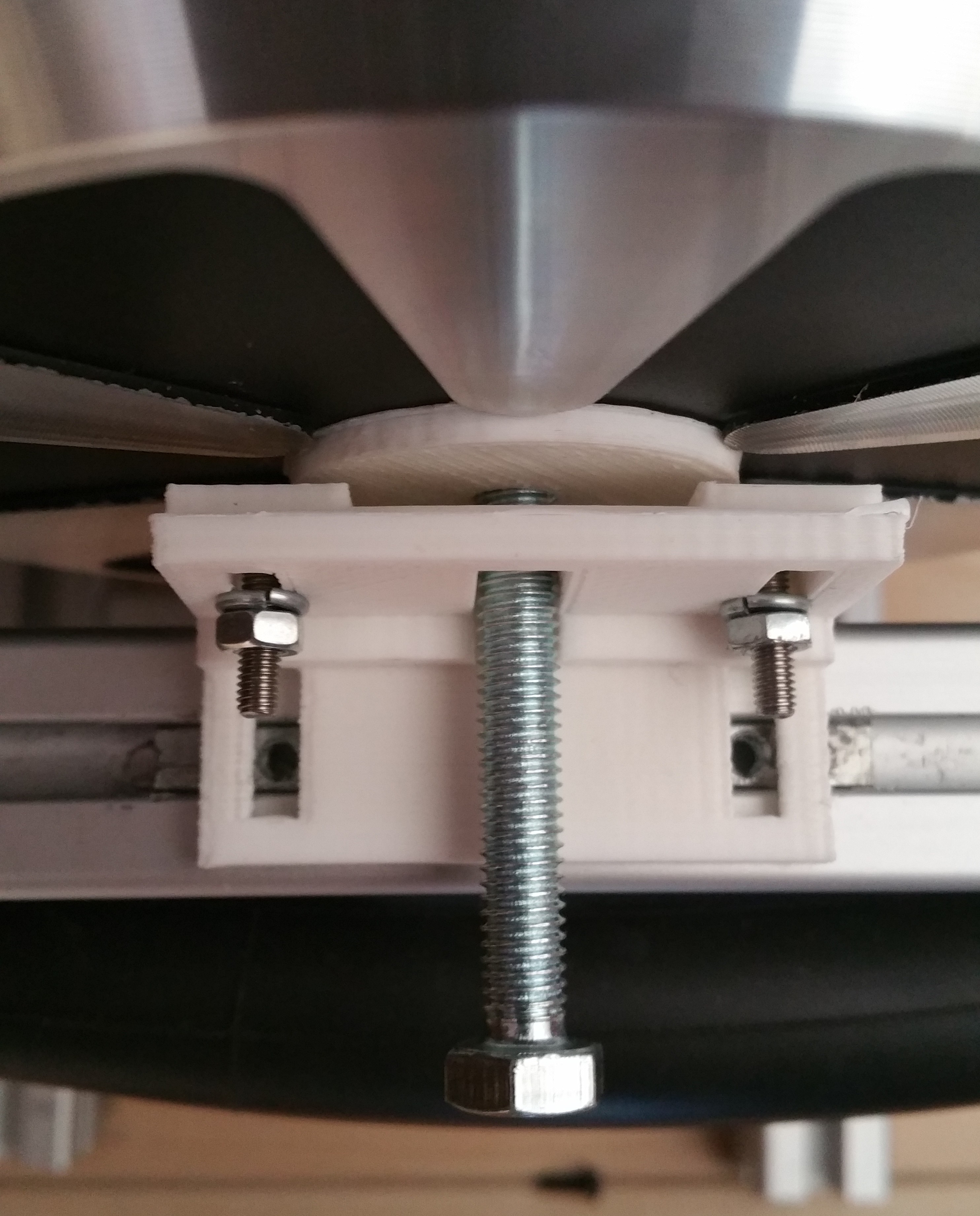
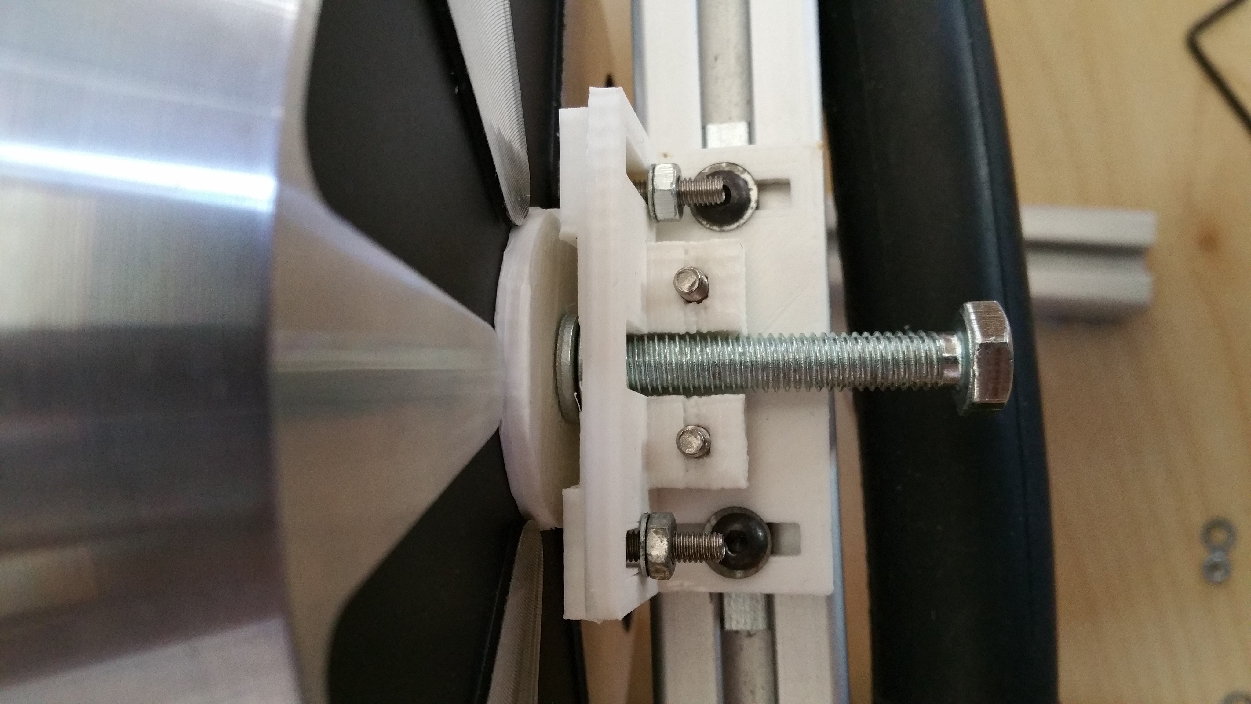
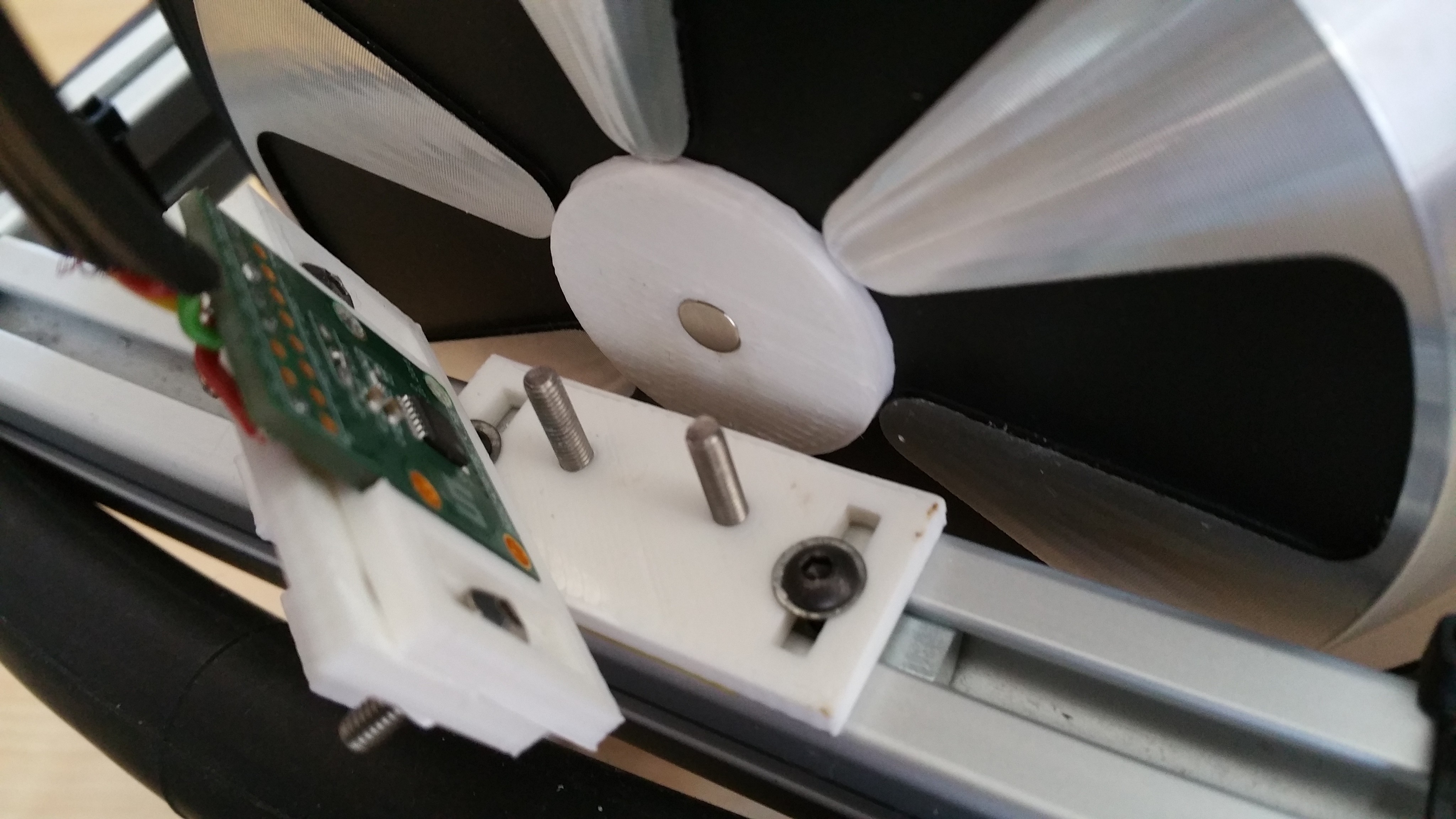
For alignment the magnet is removed from the magnet holder and a M6 bolt is placed through the sensorboard holder and in the magnet holder. The sensorboard holder can then be mounted on the bracket, retaining it position after the bolt is removed. While this designed allowed the vertical alignment of the sensorboard holder relative to the mounting bracket, it would lose the horizontal alignment when the bracket was removed in order to be able to place the magnet and sensorboard. Also the vertical part was fragile and would easily break, caused by the limited strength in the z-axis for the part. So I split the design of the bracket in two parts.
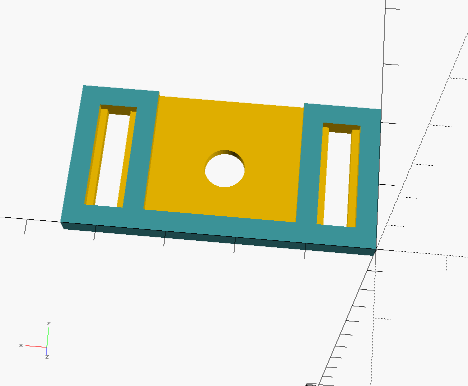
Base bracket
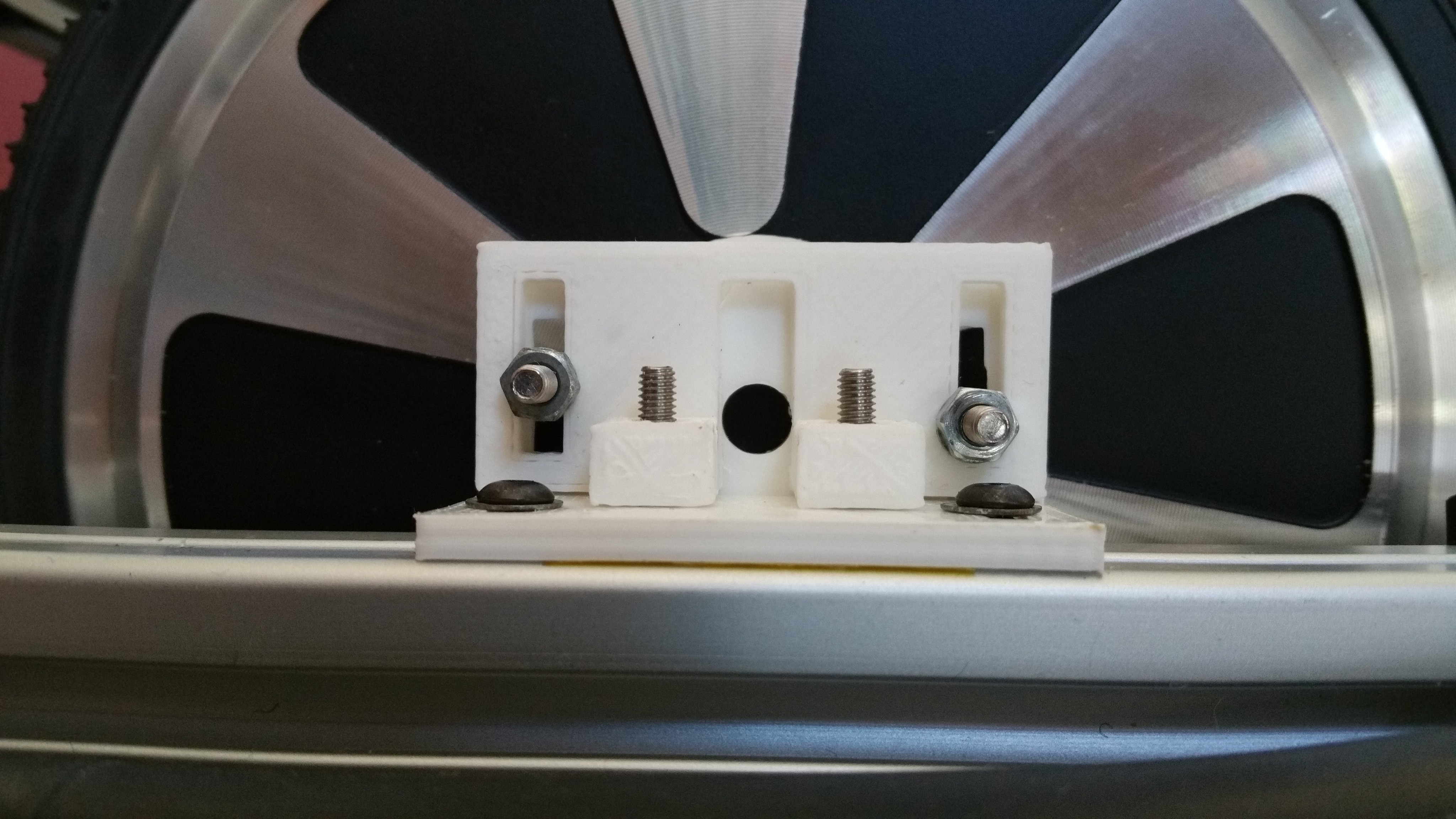
The base bracket is mounted on the T-slot profile. It has two slots to align the distance of the sensorboard to the wheel and the angle of the sensorboard to make sure it's parallel to the wheel. It uses two bolts for attaching the vertical bracket. I used two M3 bolts for MakerBeam because of their low profile and square head.

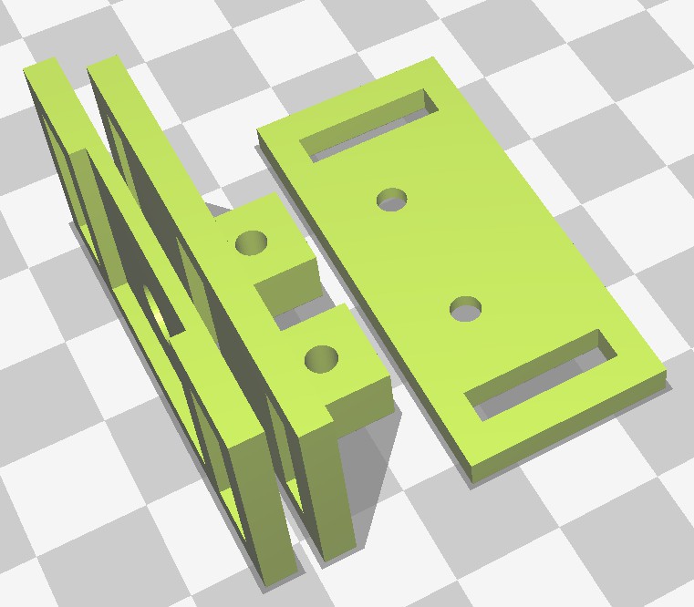
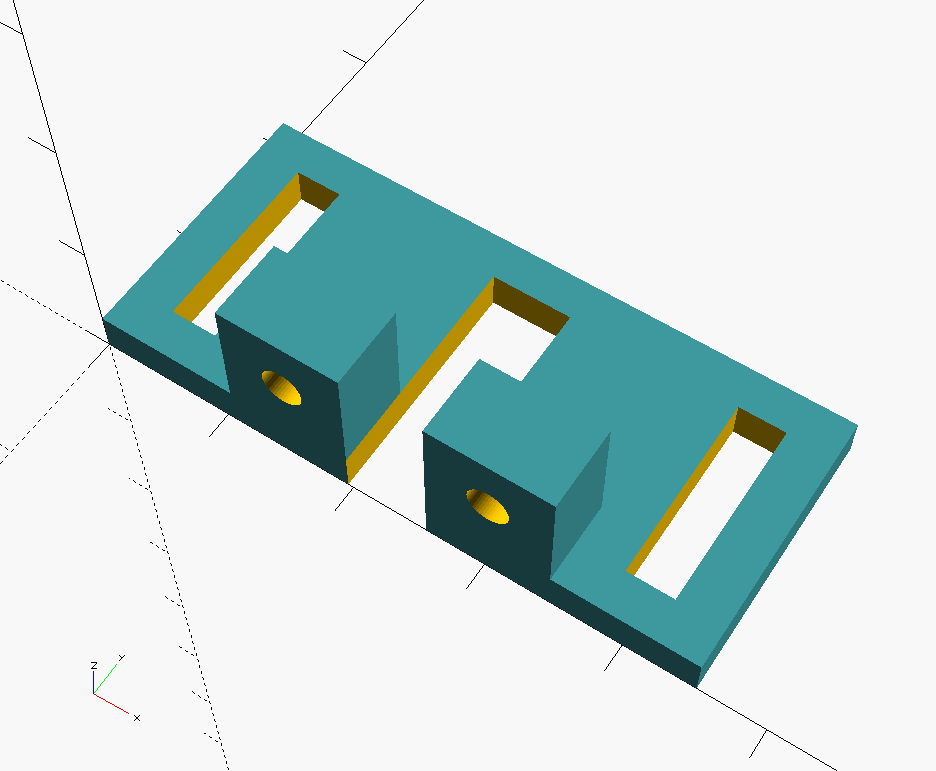
Vertical bracket
The vertical bracket is mounted on the base. Because it's now a separate part it can be printed in X/Y direction which results in a stronger part.
Sensorboard holder
The sensorboard is mounted to the vertical bracket with slots to allow adjusting the position for the alignment. It contains a cutout with the size of the sensorboard. A 6mm hole at the position the of sensor allows a M6 bolt to go through for alignment. Note: the part needs to be rotated before printing.
 In order to verify if the sensorboard is actually in the right position in the holder, I printed a sticker with the exact dimensions of the board and the position of the sensor. If the sensorboard is mounted properly, only the black area of the sensor should be visible and no purple should be visible.

Alignment process
Install the base bracket on the profile, but do not tighten the bolts yet. Mount the sensorboard holder and base vertical bracket using some m3 bolt and nuts. Tighten the nuts so that the sensorboard holder will retain its position, but still can be moved by hand.
Remove the magnet from the wheel magnet holder. Note: the design of the magnetholder could be improved with some cutouts around the magnet to make it easier to remove the magnet.
Insert a M6 bolt and some spacers to get a distance of somewhere between 0.5 to 3mm between the magnet and sensorboard. If all the parts are aligned correctly the screws for the base bracket and the bolts for the sensorboard holder can be tightened.
Removing the bolt and spacers will allow you to check the alignment.
The vertical bracket with sensorboard holder can now be removed to allow installing the sensorboard and magnet. With the sensorboard alignment sticker you can verify if the sensorboard fits properly and the sensor is at the right position.
Note: Do not forget to put back the magnet! One time I got distracted while I was working on this. When testing the motor it made a loud rattling noise and caused a partial short in the motor. End result being one motor that doesn't run smoothly any more. I may have had the current limits setup to high, but still a simple double check avoids such trouble. I ordered a second hoverboard to continue the project. I also ordered a second hand motor and hopefully I can make a working pair out of these parts. Since the outside pattern of the hub motor differ in design I had to increase the size of the magnetholder.
Design files
The design files are available in source code (for OpenScad) and STL format in the morph_design repository.
Discussions
Become a Hackaday.io Member
Create an account to leave a comment. Already have an account? Log In.