 Ted Yapo
Here's a picture of the test board running off a CR2032 cell at 33.1 uA - but half of that is just being wasted in the PIC! (see below). This image was taken in a darkened room where the display is easily visible. It appears brighter in the image than in real life, though. In a brightly lit room, it can't be seen at all at these current levels, which are about the minimum the circuit can do as built. Overall, I would judge it to be too dim to be generally useful, unless you were only going to use it in the dark - a portable GPS-synched UTC astronomy clock, for instance (I keep thinking of this one, it might become a project).
The interesting part of the circuit is shown here (not shown are decoupling capacitors):
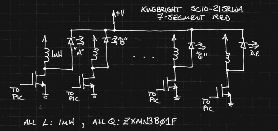
Each segment of the display is driven by a MOSFET and a 1mH inductor. The MOSFET gates are driven from PORTC of a PCI16F1718 microcontroller. To create a pulse of light from a segment, the corresponding MOSFET is driven, creating a ramp of current in the inductor. Once the desired current has been established in the inductor (just approximated by pulse length), the MOSFET is turned off, and the voltage across the inductor rises until the same current flows through an LED segment. This creates a sawtooth-shaped pulse of current through the display segment.
I used the PIC16F1718 because I had it on hand. Unfortunately, this part has an internal low-dropout regulator that draws 15 uA even during sleep mode (datasheet typical number). In my first tests, periodically waking every 32ms to pulse the segments, the PIC draws 16.4uA even when lighting no segments. Although you can disable the LDO during sleep, you pay a penalty in the wake-up time. I haven't measured it, but the delay is long enough to make the display flicker in a very annoying way. I really need to use an "LF" PIC variant. I like the '1718 overall, so I'll probably pick up some LF's with my next DigiKey order.
So, the first test was a simple assembly program that wakes every 32ms to create a current pulse of 8us. This is the lowest-power TritiLED mode. The code is a simple counter, incrementing the hexadecimal digit on the display every 255 timeouts of the WDT, or about every 8 seconds. This is long enough for me to measure the current draw with each digit displayed. Here are the results for digits 0-9:
| Digit | Current (uA) |
| 0 | 34.6 |
| 1 | 21.7 |
| 2 | 31.6 |
| 3 | 31.7 |
| 4 | 26.4 |
| 5 | 29.4 |
| 6 | 33.1 |
| 7 | 26.4 |
| 8 | 36.8 |
| 9 | 31.1 |
I assume the current draw for digits with the same number of lit segments is slightly different due to the inductor tolerances. The average over all digits is 29.3 uA. Considering that over half of this is wasted in the PIC LDO during sleep, the results aren't that bad. It also means that you might get much more brightness for small incremental current increases.
Notes/Observations
This is the lowest current I can run with this circuit. I will experiment with running higher currents. It looks like something in the 100 uA range would make this display usable.
The red color isn't great for nighttime visibility. I found some very bright green displays (for $7.78 each!) on DigiKey. I think I will have to buy one. They're common anode, which will mean a re-think of the circuit - the easiest way might be to use P-channel MOSFETS. The green color should look much brighter to dark-adapted eyes, and these displays are about 2x brighter even in normal lighting.
The display can't be seen in normal room lighting, unless you add a red contrast enhancement filter. The problem with filters is that even though they improve contrast in some lighting, they always make the display darker. In a dark environment, contrast-enhancement filters make things worse. They certainly do in this case.
@Elliot Williams mentioned possibly just using a current-limiting resistor and PWM to drive LEDs at low brightness. This might be an easier alternative if the supply voltage was stable and always enough to light the LEDs. On the other hand, the inductor scheme can work with supply voltages down to the minimum of the PIC, 1.8V from the datasheet, and somewhat lower (off-label). Even with higher voltages, the inductor scheme might be more efficient than using resistors.
Here is the assembly test code:
#include <p16f1718.inc>
  ERRORLEVEL     -302
  ERRORLEVEL     -305
  __CONFIG  _CONFIG1,  _FOSC_INTOSC & _WDTE_ON & _PWRTE_ON & _MCLRE_ON & _CP_OFF & _BOREN_ON & _CLKOUTEN_OFF & _FCMEN_ON
  __CONFIG  _CONFIG2,  _WRT_ALL & _PPS1WAY_OFF & _ZCDDIS_ON & _PLLEN_OFF & _STVREN_OFF & _BORV_LO & _LPBOR_OFF & _LVP_ON
;;;
;;; variables
;;;
  cblock  0x20
    digit
    counter
  endc
;;;
;;; reset vector
;;;
    ORG         0
    call        SETUP_PERIPHERALS
    BANKSEL     LATA
    movlw       .63
    movwf       counter
    clrf        digit
MAIN_LOOP:
    decfsz      counter
    bra         PULSE
    movlw       .255
    movwf       counter
    incf        digit
PULSE:
    movf        digit, W
    call        SEGMENT_LOOKUP
    movwf       LATC    ;; start pulse
    ;nop
    ;nop
    clrf        LATC    ;; end pulse
    sleep
    bra         MAIN_LOOP
SEGMENT_LOOKUP:
    andlw       0x0f
    addwf       PCL
    retlw       b'01111101' ; 0
    retlw       b'00101000' ; 1
    retlw       b'11100101' ; 2
    retlw       b'11101100' ; 3
    retlw       b'10111000' ; 4
    retlw       b'11011100' ; 5
    retlw       b'11011101' ; 6
    retlw       b'01101000' ; 7
    retlw       b'11111101' ; 8
    retlw       b'11111000' ; 9
    retlw       b'11111001' ; A
    retlw       b'10011101' ; b
    retlw       b'01010101' ; C
    retlw       b'10101101' ; d
    retlw       b'11010101' ; E
    retlw       b'11010001' ; F
SETUP_PERIPHERALS:
    ;; intosc 500 kHz
    BANKSEL     OSCCON
    movlw       b'00111010'
    movwf       OSCCON
    ;; setup WDT for 16ms timeout
    movlw       b'00001001' ; 16ms
    movlw       b'00001011' ; 32ms
    movwf       WDTCON
    ;; turn off LDO reg for low-power sleep
    ;BSF         VREGCON, VREGPM
    ;; select digital I/O
    BANKSEL     ANSELA
    clrf        ANSELA
    clrf        ANSELB
    clrf        ANSELC
    ;; set TRIS bits: all outputs
    BANKSEL     LATA
    clrf        LATA
    clrf        LATB
    clrf        LATC
    BANKSEL     TRISA
    clrf        TRISA
    clrf        TRISB
    clrf        TRISC
    return
    END
Discussions
Become a Hackaday.io Member
Create an account to leave a comment. Already have an account? Log In.