 Ted Yapo
The first test used an inductor per LED segment. This works, but would be bulky and expensive for larger displays. I simulated using P-channel MOSFETs to switch the LEDs using a common boost inductor:
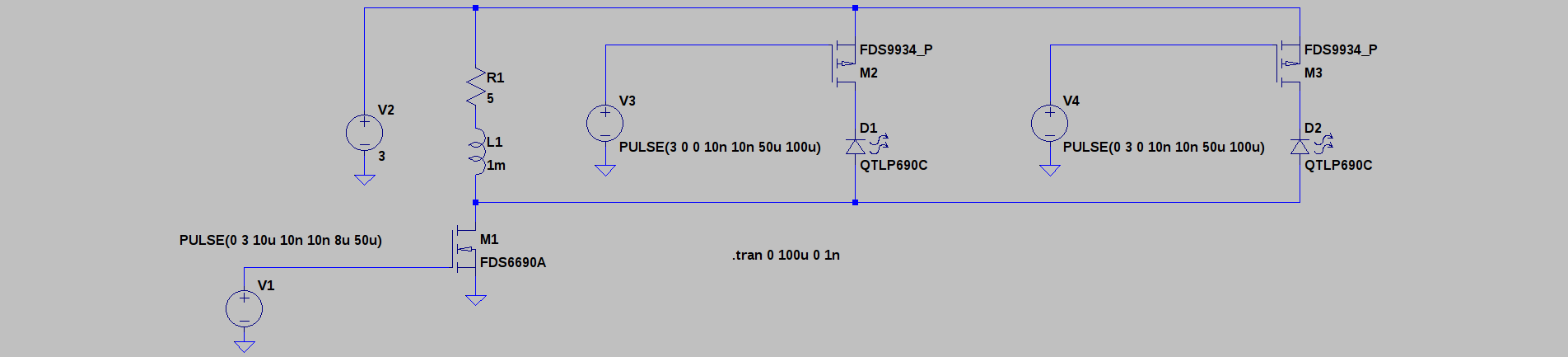
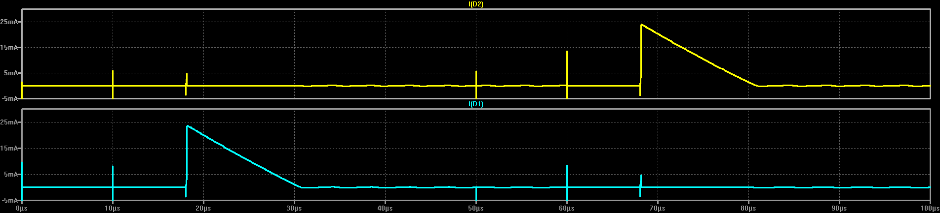
The LEDs and specific MOSFETs in the circuit were just conveniently in the LTspice library - I have no idea if they are actually suited to this application (I didn't check the Vgs vs Id curves, for instance). In this simple test, one LED is first enabled by pulling the gate of its respective MOSFET low, a current pulse is generated by the inductor, and the discharge flows into the first LED. The second LED is then enabled and receives its current pulse:
This high-side switching could be used in two ways:
- A common-anode display could be driven directly with this circuit; the original test required a common-cathode display.
- High-side switching for common cathode displays combined with the original inductor-per-segment would drive multiplexed multi-digit displays. Since the duty cycle of the current pulses is already very low (0.025 - 0.05%), multiplexing can be done without affecting the perceived brightness.
I haven't built a circuit like this yet, - I'm still waiting for some suitable P-channel transistors, but from the simulation, it looks like it is going to work.
Discussions
Become a Hackaday.io Member
Create an account to leave a comment. Already have an account? Log In.