 I'm a maker
In general, the hall effect sensor is switching when a magnet is close to it. Thus, we have to attach the hall effect sensor to one part of the axis of the CNC machine and a magnet to the other part. For a detailed description how hall effect sensors work, please read the Wikipedia article (Hall effect sensor on Wikipedia).
To use the hall effect sensor given in the component list, +5V power supply is required. Since most of the break-out-boards have a +5V supply, it should be possible to use that directly. The SS 441 A sensor requires about 20mA. Thus, for 3 axes with each 2 sensors we require 6*20mA = 120mA. Hopefully, your break-out-board can deliver this current. Otherwise, you require another power supply unit.
The current version of the schematics (and board) include a LED that lids up if the hall sensor switches. The LED requires about 20-25mA, so that the power supply should deliver this additional current. Of course, it is possible to ignore the LED when soldering. In this case the 1kΩ resistor, the 120Ω resistor and the transistor can be ignored as well.
For this project there are some requirements to mill the PCBs, solder them, mill the housings and attach them to the CNC machine:
- CNC Machine (possible w/o limit switches, of course)
- V-Carving bit (the smaller the better, I use this one: Stepcraft V-Router)
- End mills to cut the hall effect sensor PCBs
- Different end mills to mill the housing (dependent on the final design)
- Soldering iron
- Components (see component section)
- Break-out-board with inputs for the axes and +5V power supply (alternatively, an additional power supply unit)
PCB Schematics
It is important to notice that we are developing two different schematics that differ in the output of the hall sensor. Thus, regarding to your break-out-board, you can choose one of these schematics.
1. Schematics with output +5V/GND
The following layout shows the hall sensor board with just a few components. The hall sensor SS441A requires +5V and GND and delivers two different outputs:
- +5V, if the hall sensor is not active, i.e., no magnet close to the sensor
- GND, if the hall sensor is active, i.e., a magnet is close to the sensor
For the SS441A just one other component is required, the 10kΩ resistor R2. The remaining components are just to control the LED (transistor, resistors and LED).
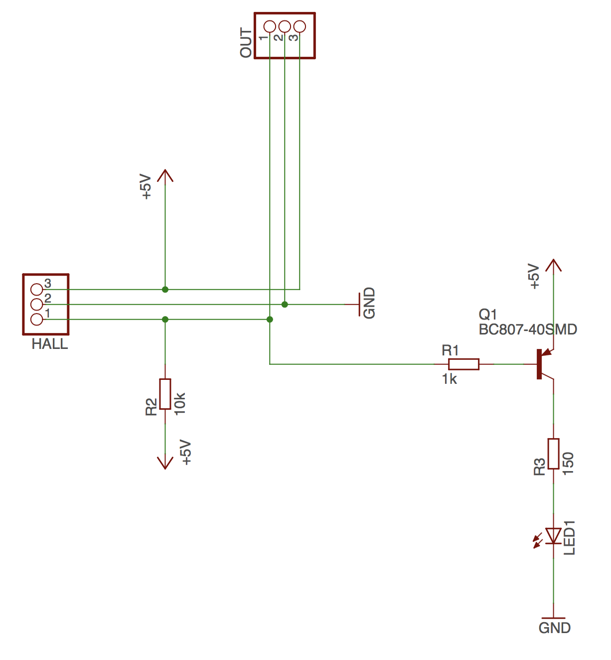
The hall sensor has to be soldered to the HALL pin header. The pin header OUT is the connection to the CNC break-out-board where pin 1 is the signal, pin 2 is the connection to ground and pin 3 is the connection to +5V.
2. Schematics to close a connection
The components in this schematic are basically the same. There are just a few more components which take the output of the hall sensor as input and close the connection, e.g., for break-out-boards that require a closed connection between two pins (e.g., Example break-out-board).
The new components in this schematic are:
- Opto-coupler
- Resistor
The required resistor depends on the LED in the opto-coupler. In general, the data of the LED is given in the datasheet. In this project we are using the LTV816, since the component is available in standard EAGLE libraries and it suits our requirements.
PCB Board
The board file of EAGLE is attached. Of course, you are free to change the layout of the board to suit your personal.
Milling
In this project we don't want to describe the mechanism to mill a PCB in detail. There are a few steps required to mill them correctly. First, the PCB material has to be level or probed to be level. See the following links depending on your machine, how to autolevel the PCB material:
If you designed your own PCB layout please make sure that there are no unconnected copper areas since they can influence the noise level of the schematics and especially influence the output.
Soldering
Soldering of the PCBs is just straight-forward. It is important that a few components are soldered the right way. It does matter for
- LED
- Opto-coupler (with second schematics)
For the LED, it is important that...
Read more »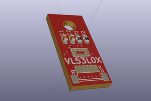
 Martin Pålsson
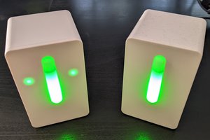
 Stefan Lochbrunner
 Amar Potdar