 will.stevens
The joule thief is a very simple circuit to make. The Wikipedia article about the joule thief describes the circuit and how it works. This page has a helpful description of boost converters, which helps with understanding the joule thief circuit.
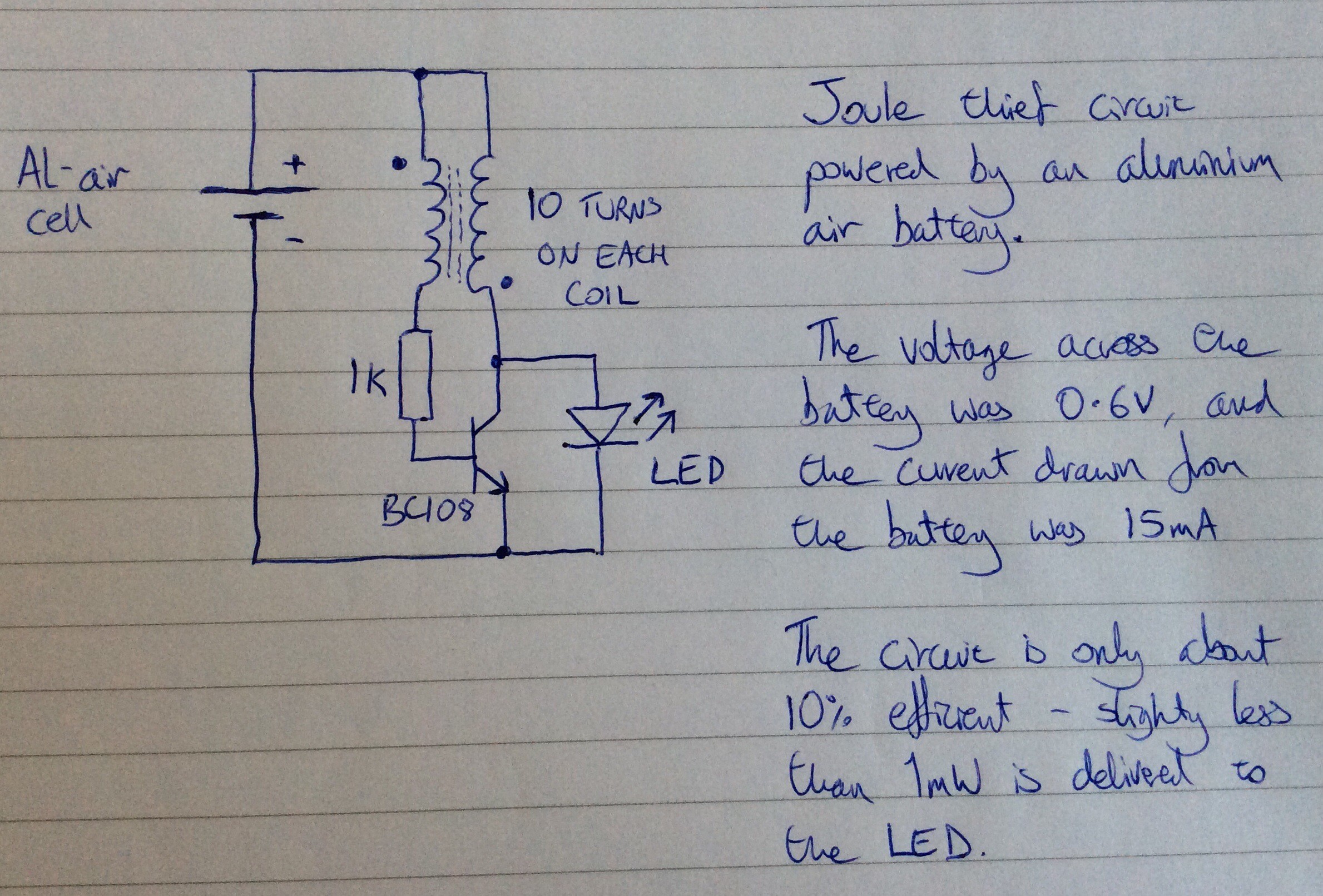
Below is the circuit diagram for the variant that I made:
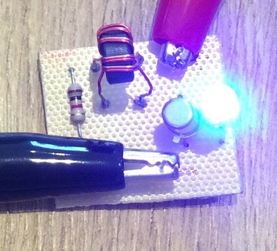
And here is a photo of the circuit:
Any general purpose NPN transistor should work. The ferrite ring transformer that I've used was salvaged from an old computer circuit. It has 10 turns per coil, but I believe that a larger number of turns (20 say) would result in a more efficient circuit.
The power being input to the circuit from the Al-air cell is about 5mW, and the power being supplied to the LED is about 0.5mW, so the efficiency of the circuit is only about 10%. The power output from the cell varies over time. Initially it was 9mW. It slowly declines, in part because the water in the electrolyte both evaporates and gets used up in the anode reaction. The water needs to be topped up periodically (once a day). Whenever the water is topped up the power output increases again.
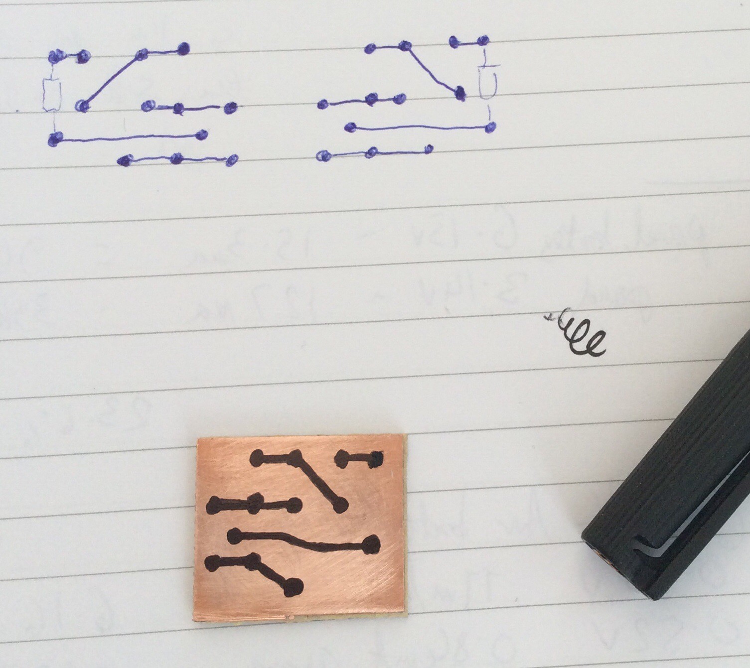
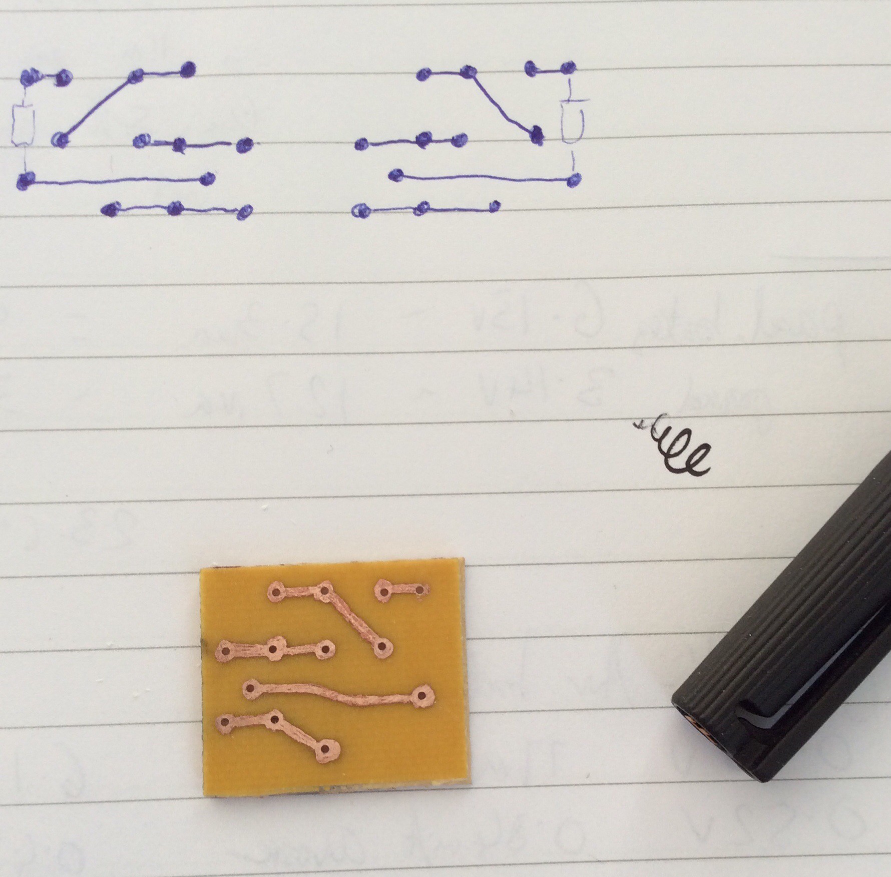
The PCB was produced by hand-drawing the tracks, as shown in the before and after etching photos below. For small circuits like this hand-drawing is quick. I find it helpful to first draw the tracks on paper as if viewed from the component side, then draw the mirror image, then draw onto the copper-clad board.
Discussions
Become a Hackaday.io Member
Create an account to leave a comment. Already have an account? Log In.