 will.stevens
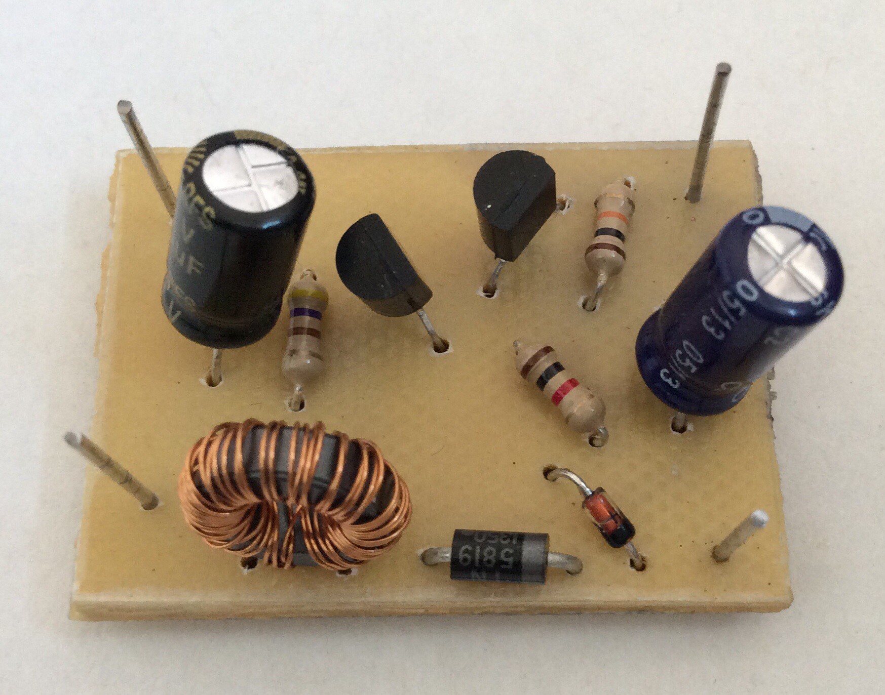
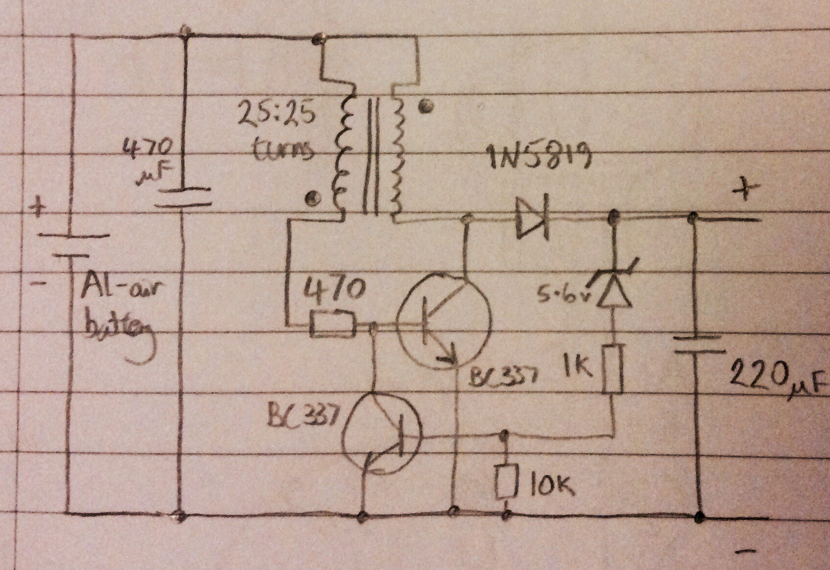
This is a more efficient joule thief than my first attempt, shown in an earlier log entry. The efficiency of this circuit (i.e. power output from circuit / power output from Al-air battery) is about 60%. (My first attempt was only about 10% efficient. I believe that either the choice of transistor was incorrect on my first attempt, or I didn't have enough turns of wire on the transformer).
The voltage produced by the circuit is regulated - the Joule thief discharges into a capacitor, and the Zener diode effectively turns the joule thief off when the target voltage is reached, and on again when the voltage begins to drop. Initially I used a 5.1V Zener diode, and found that this resulted in 4.6V at the output. A 5.6V Zener diode gives 5.5V at the output. After making this I found an almost identical circuit here: http://www.electro-tech-online.com/articles/the-scavenger-a-joule-thief-inspired-boost-regulator.594/
(The circuit in the link has a couple of extra components which I believe are to help prevent potential transistor damage damage and to smooth out ripples at the output).
Discussions
Become a Hackaday.io Member
Create an account to leave a comment. Already have an account? Log In.
I added a MOSFET to my design for switching. :)
https://hackaday.io/project/2138-discrete-inverter-for-led
Are you sure? yes | no
There are 3 efficiency improvements in the other circuit.
In your circuit you have a 470 Ohm resistor (series bias to oscillating transistor) and that low value is shunting the high energy from the transformer for two reasons.
1) Simply it's low value - use a higher value resistor with a higher gain transistor like a Darlington.
2) The extra capacitor (C2) in the other circuit averages the feedback so that feedback transistor is not trying so hard to drive the oscillating transistor off.
The third efficiency improvement is the rectifying diode. Most diodes have a forward voltage of around 0.6 volts and that represents a power inefficiency of around 19% if you use a lower junction voltage diode then it will improve the efficiency a lot.
I would probably also put a resistor between the feedback transistors collector and the base of the oscillating transistor as a divider. A low gain transistor is fine for the feedback transistor.
All looks good though, I like it.
Are you sure? yes | no
1N5819 in the circuit is a schottky diode.
Are you sure? yes | no
It's a very old silicon schottky barrier diode and you almost certainly need a fast switching diode like this but it's forward voltage (from the datasheet) is 0.6 volts (@ Imax) to 0.9 volts (instantaneous). That's not any better than a silicon PN diode apart from the switching speed. Some silicon PN's get down to 0.4 volts.
I modern replacement will get you down to 0.2v and switch even faster so that it is not working in the linear range when switching off. A (MOS)FET would be even better.
Here is an example (there are much better ones out there) -
http://www.onsemi.com/PowerSolutions/product.do?id=NSR0320
that is PIV = 20v, IFmax = 1A, VF = 0.24v @ If = 10mADC
This would greatly improve efficiency or as mentioned a FET would be even better.
From your component selection, it seems that you have been in the industry for a long time. :)
I love the idea of a aluminium (aluminum) air cell powered joule thief!
Are you sure? yes | no
>use a higher value resistor with a higher gain transistor like a Darlington.
The saturated voltage of a Darlington transistor includes a B-E drop so you are looking at 0.8V and higher for VCE which is not suitable for operating from 1.2V of a Al-air battery.
There are high gain transistors without restorting to those.
Are you sure? yes | no
Agreed, you have to be careful choosing a Darlington. The biggest problem is usually Cbe of the hidden junction but some Darlingtons have a resistor Rbe internally. The Vbe isn't such a problem with a common emitter as you can just reduce the Zener voltage but common collector is always a problem.
A straight bipolar with higher gain is probably best.
Have a google (image) for mosfet rectifier some tips
Are you sure? yes | no
See my URL at the top for my hybrid project. I use a MOSFET in parallel with a transistor with the MOSFET gate connected before the resistor. The transistor sets up the beginning of a cycle. As the voltage builds up the MOSFET turns on and handles most of the switching current. According to the simulation, it runs at about 80% efficiency and can go much higher power. :)
Are you sure? yes | no