 Ben Holmes
Specification
| Parameter | Value |
| Input voltage | 5 V |
| Output voltage | 3 V |
| Output current (max) | 300 mA |
Notes
The Pocket Operators were measured to find their current draw, which is around 30 mA RMS.
Micro USB to 3 V power supply for the Pocket Operator
Already have an account? Log in.
To make the experience fit your profile, pick a username and tell us what interests you.
| Parameter | Value |
| Input voltage | 5 V |
| Output voltage | 3 V |
| Output current (max) | 300 mA |
The Pocket Operators were measured to find their current draw, which is around 30 mA RMS.
PO-PSU kicad.zipAll kicad files for the PO-PSU project.Zip Archive - 131.94 kB - 08/11/2017 at 05:32 |
|
|
3405fa.pdfDatasheet for the regulatorAdobe Portable Document Format - 286.06 kB - 08/11/2017 at 05:29 |
|
|
PO-PSU schematic.pdfPDF version of schematicAdobe Portable Document Format - 23.79 kB - 08/11/2017 at 05:29 |
|
|
Digikey BOM rev 2.csvBOM for revision 2 PCBComma-Separated Values - 711.00 bytes - 08/10/2017 at 05:26 |
|
|
I'm signing this project off as finished as I don't intend on doing another board revision, the second revision accomplishes the design goals. The remaining work I intend on doing is writing up about points of interest, and ensuring the BOM and CAD files are up to date.
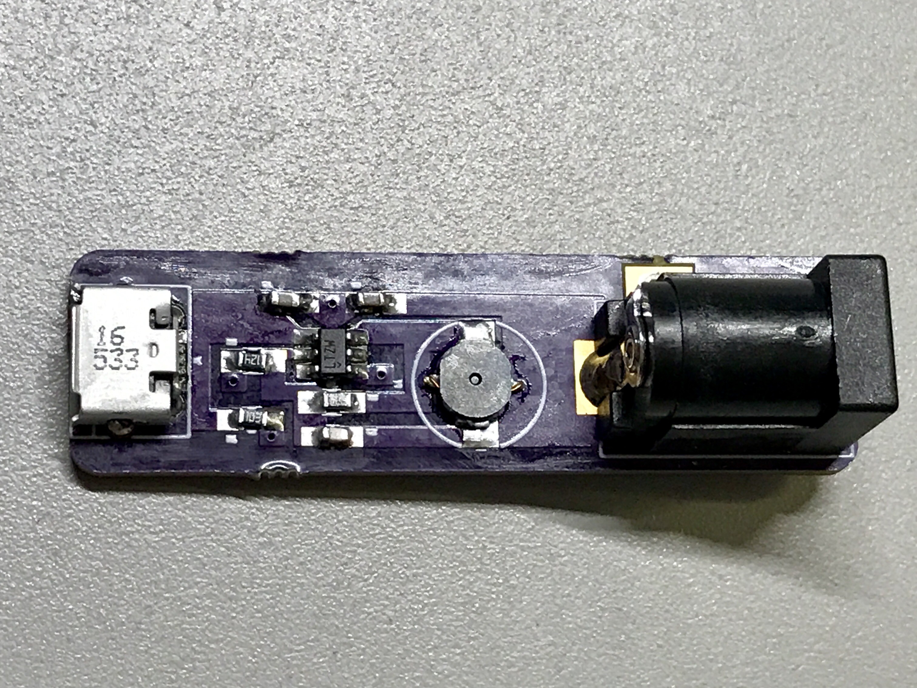
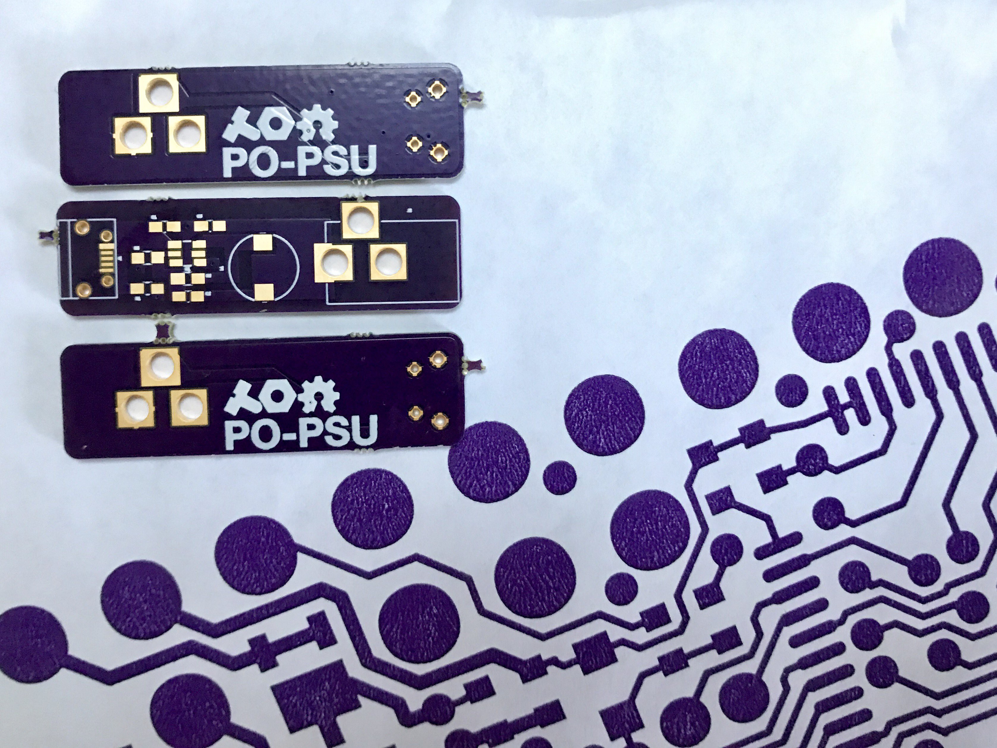
Here are a couple of close-ups of the second revision:
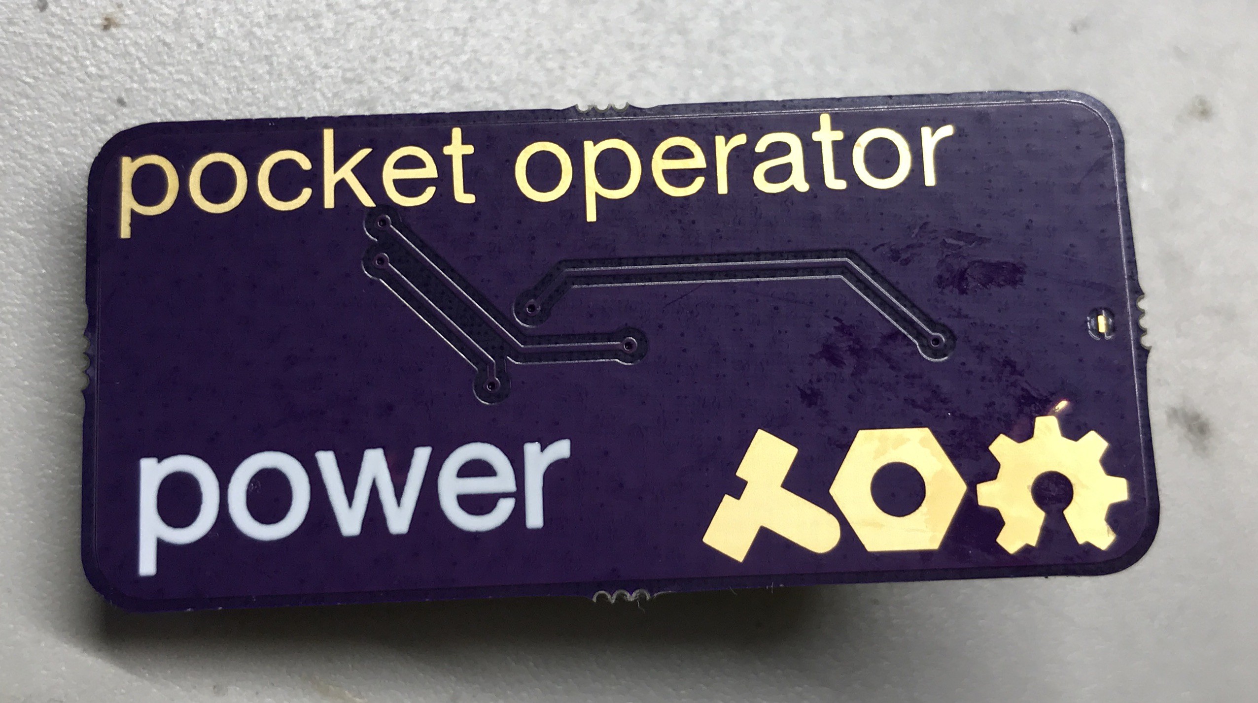
I used exposed copper on the bottom to replicate the pocket operator visuals.
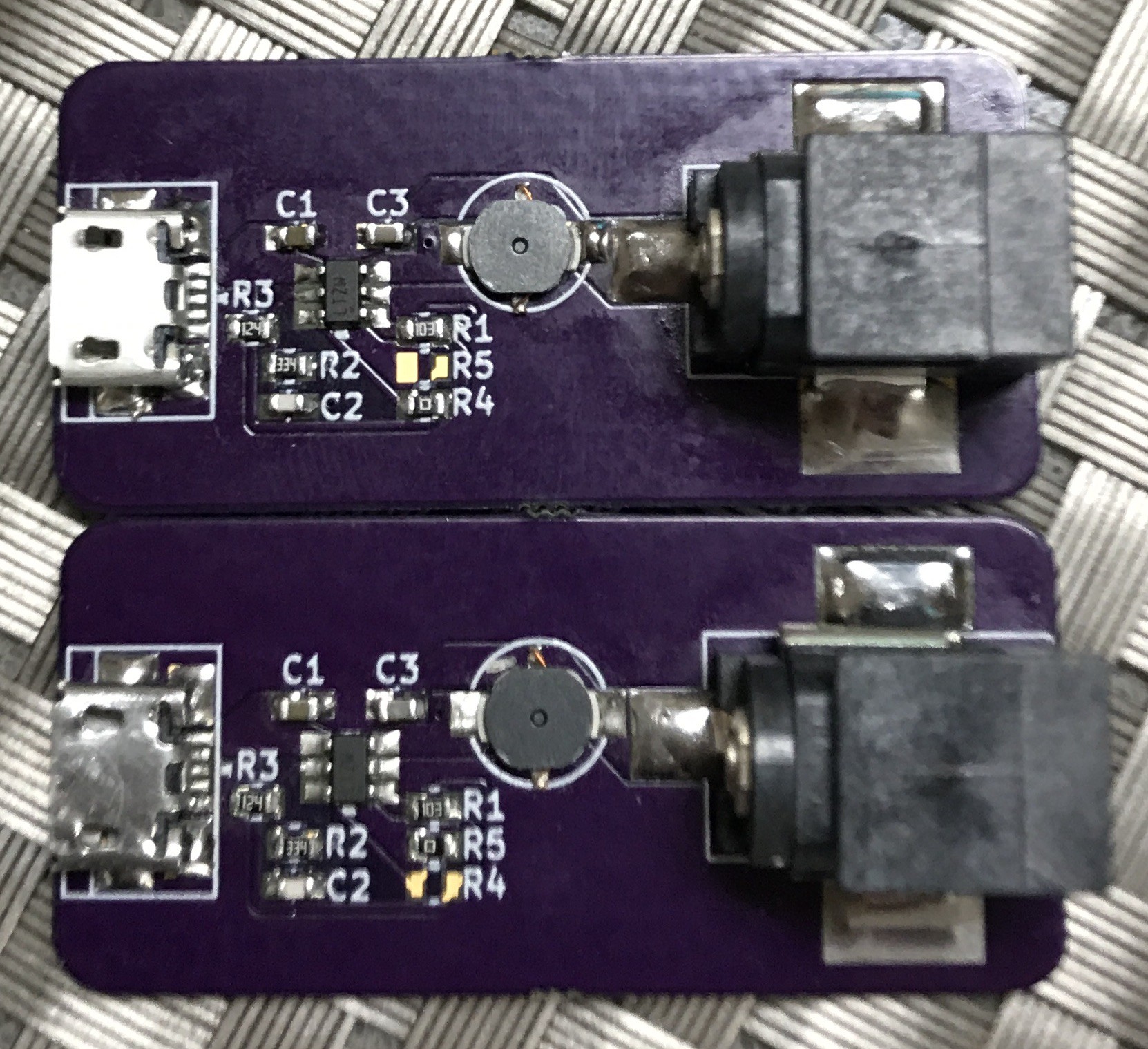
Two versions of the hardware exist: one with burst mode enabled and the other using traditional pulse skipping. R4 enables pulse skipping, R5 enables burst mode (stuffing both leads to a damaged USB port).
The second revision is finished and functional! Here it is in action: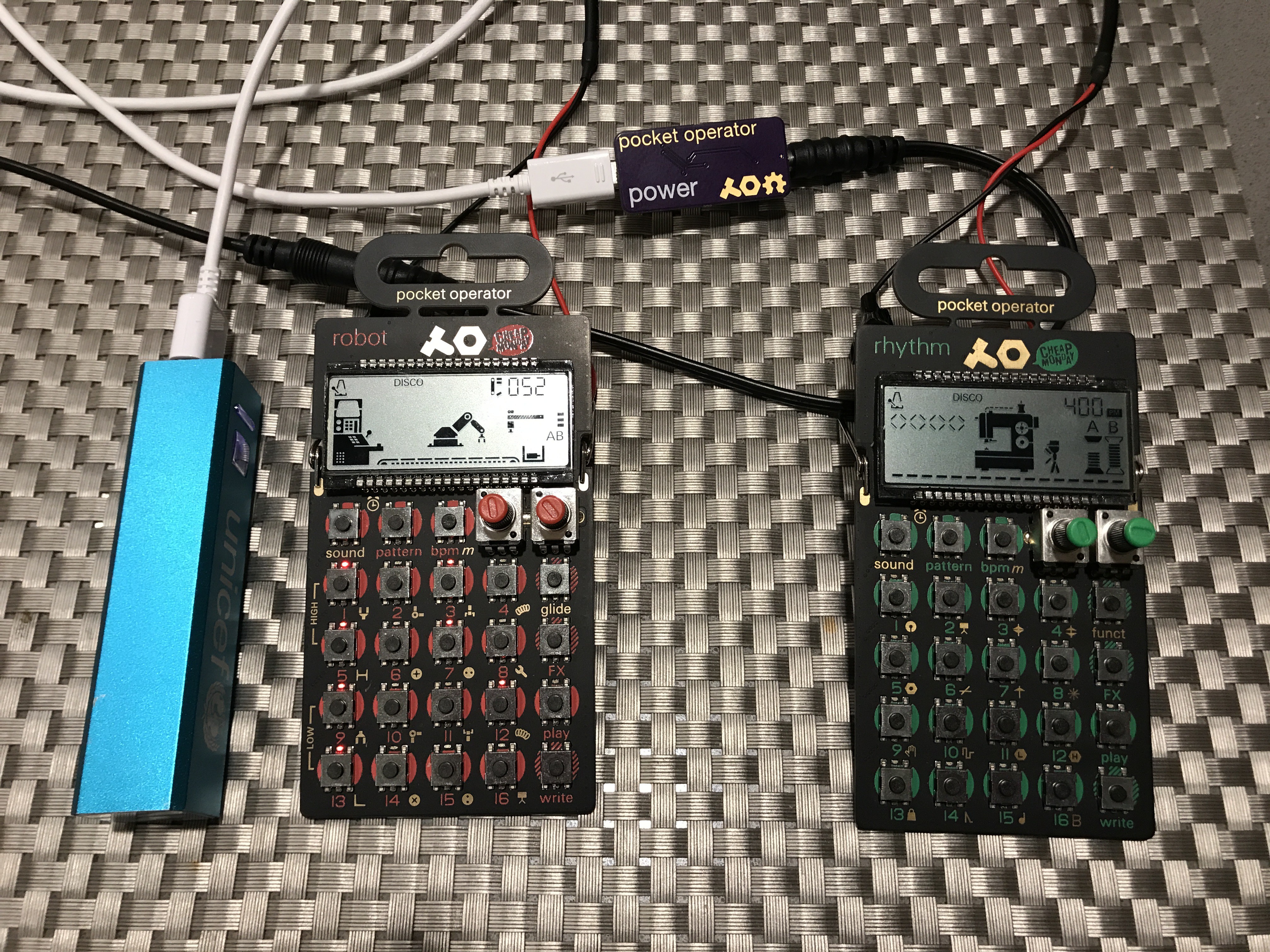
As you can see it is happily driving my two pocket operators from one USB battery (the blue thing on the left).
Modifications to this revision:
New files will be updated when I have time.
Using the first round of builds (minus the USB jack and with a couple of mod wires attached) the project has now been tested on some dummy loads.
With no load, there is 140 mV ripple current in the output.
| Load | 100 Ω (30 mA) |
| Output Voltage | 2.98 V |
| Output ripple | 80 mV |
| Bench supply current | 20 mA |
| Efficiency | (2.98^2/100)/(5*0.02) = 88.8 % |
| Load | 3 x 100 Ω in parallel (90 mA) |
| Output Voltage | 2.91 V |
| Output ripple | 60 mV |
| Bench supply current | 58 mA |
| Efficiency | ((2.91^2)/(100/3))/(5*0.058)= 87.6 % |
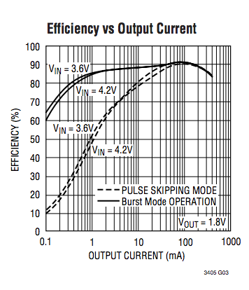
This shows that PO-PSU can generate enough current for three POs without dropping the voltage significantly. The efficiency numbers seem good, although they are very approximate as I didn't measure the value of the resistors so they could be ±10%. The device is currently configured in burst-mode which offers better efficiency at low output currents, but it may be worth testing the device in pulse-skipping mode to see if there is a large loss in efficiency. Pulse-skipping mode is stated in the datasheet to offer better output ripple so would be nice to reduce the noise transmitted to the PO.
Just an update on the inspiration: the link to the product I copied can be found here. I copied more than I remembered, all the way down to the name! However I stand by the purpose of this project, to open source a design (and also to make a design that doesn't require modifying the PO).
Further design analysis looks like the voltage converter is an LM317 or something similar. If this is the case (big if) then there are numerous possible advantages:
The part (LTC3405) I am using instead does have several negative aspects though:
Specifically, the LTC3405 has a mode designed for operating at very low current draw which is attractive as there may not always be a PO connected. Further, the designed as it is at the moment disables the LDO if there is no jack present in the DC connector. Both of these prevent wasting energy.
Having populated the board and testing the design there need to be some revisions.
Revisions:
However, the circuit works properly, generating a solid 3 V! Only 1% error with no load (multimeter).

The first prototype run of boards has arrived from OSH Park! Looking very pretty.
The parts arrived from Digikey last week so all I need is some time to build it up. Testing the through-hole components in their places reveal the DC jack to fit very loosely as KiCAD doesn't support slotted plated holes. As well as this, the micro USB doesn't fit the front holes and will have to have the pins bent into place. I suppose this is why we do prototypes!
 Alex Klimaj
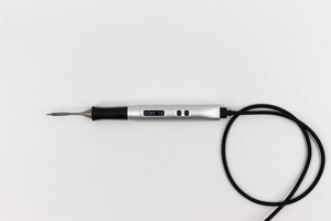
 Nicolas Schurando
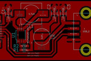
 SUF
SUF