 Evangelos Petrongonas
Welcome to the first out of two (or three) DesBlogs, where we will discuss the theory and the construction of the Sensor.
In this first one lets discus about the theory that makes the idea doable.
The theory behind the sensor is pretty simple and straightforward, as it is based on the Capacitor Charging phenomenon.
Firstly let’s remember what affects the Capacitance of a parallel plate system. According to the well-known relation C= (A.er) /d , where A is the area of the plates, er is the dielectric permitivity of the material between the plates and d, is the distance between the plates.
Let’s Consider now
that both A and er, are constant. As a result the Capacitance is
inversely proportional to the distance. That is very important
deduction, as now we know that by measuring the capacitance, we can
find the distance between the plates.
Now consider that
one plate is a plane of a three dimensional axis, and the other plate
is a hand (or any other grounded object). By having three of
these plates, placed in a way that that are pair-wise perpendicular,
we create a Cartesian coordinate system, where the object can be
represented in.
Enough with the
Math, at least for now, let’s move to the next big Design Puzzle,
which is, how can we measure the Capacitance?
The answer is we don’t…. kind off….
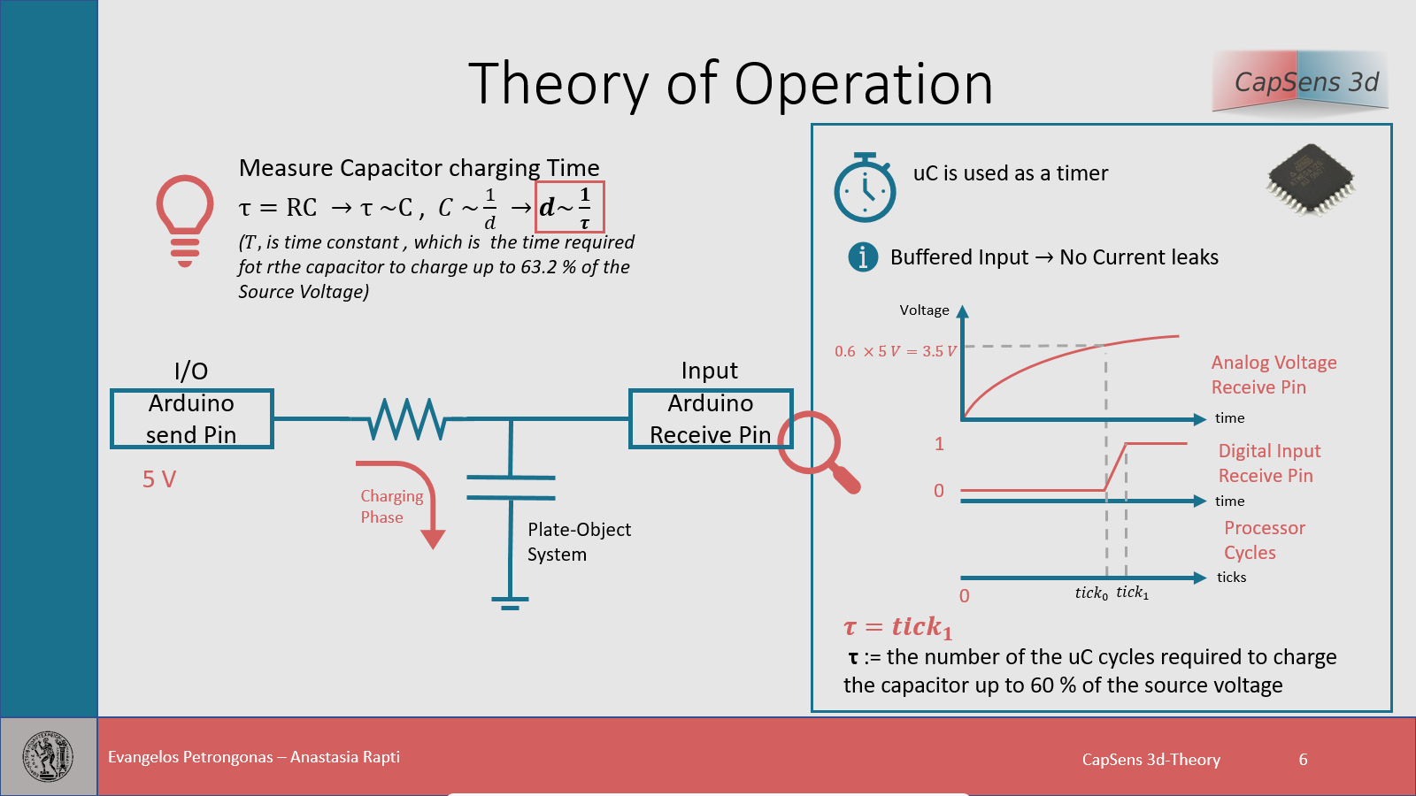
Before we clarify the above statement, let us take about microcontrollers and more precisely, the way they can interact with environment. A uC, can “sense” only three things. Time, Analog Current (using the ADC’s) and Digital Levels 0,1.
As you can see Capacitance is not one of them
BUT,
after some more math we come up to the famous time constant. Time constant (t) is the time that it takes the capacitor to charge up to the 63 % of the supply voltage, when charged through a resistor. More over τ = RC, so τ ~ 1/d. Congratulations ! the distance is now linked to a value that the uC can measure, but we still have to figure out how to find the time constant. One may think to measure the voltage of the capacitor directly using the ADC’s, but there is a more efficient way of doing it by using the RTFM method (if you don’t know what RTFM means, I strongly suggest you to google it. In order to give you a hint R stands for Read…). The Digital Input Pins of the uC are buffered and a Comparator is used in order to determine whether the Sense Voltage level is 0 or 1. If the Anlog (let’s assume DC) input voltage is greater than the threshold voltage the it reads 1, or 0 otherwise. The threshold voltage for the mega328p (Arduino UNO), is 0.6 time the Source voltage, which is very close to the 63 % of the time consant.
Voila, the time constant is equal to the time it take for the input to go HIGH, while this is accomplished simply by connecting directly every plate to an Arduino Pin.
One more step is
required and we are ready. In order to display distance we convert
the time measured to a normalized distance approximation based on
some more math and the Calibration Curves, which luckily you don’t
have to make, since we have done them for you :)
In conclusion,
everything that is mentioned below can be summed up in the following
picture.
Stay tuned for the next DesBlog where we will discuss the Design Choices and limitations.
Until Then,
keep hacking,
Evangelos.
Discussions
Become a Hackaday.io Member
Create an account to leave a comment. Already have an account? Log In.