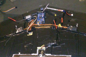
• Much Ado About Busses

    Ryan Spicer03/29/2018 at 02:06 0 comments

    One of the key requirements I set up for this project is the ability to interchange the "button boxes" on the end of the collective to match the switchology of different helicopters that I might simulate. I also wanted to be able to configure the throw of the collective lever to match different platforms: within DCS, the Ka-50 attack helicopter's collective barely moves from the horizontal, while something like the Mi-8 or Gazelle has something more like 30-40 degrees of travel. To address this challenge  I went through several revisions of the concept to get to where I am now: PCBs out to oshpark for fabrication and components in flight from Mouser.

    My initial thought was to use several 74HC165 shift registers to convert parallel switch inputs to a serial line, to connect to the microcontroller in the base. This is the approach that Thrustmaster uses in their Warthog and Cougar lines: microcontroller in the base and each interchangeable grip contains two 165s.  The good news is, this is pretty simple to set up: you need six lines: voltage, ground, clock, clock enable, latch, and serial out lines from the 165s to the microcontrollers, but the code for an arduino-ecosystem board is readily available. The bad news: you need pull-ups for each parallel input, which means either fun with routing resistor packs, or a bunch of individual resistors. Also, because of the way 165s daisy chain, I could not find an easy way to avoid hard-coding the number of 165s in the system. In practice, every control grip I'm looking at has between 10 and 16 buttons, so two 165s could cover everything, but I didn't want to restrict my ability to add analog inputs later. 

    The next thought was to use an ATMega acting as an I2C slave in each grip, and connect the 165s and/or any additional IO gear to the ATMega165. Using I2C means that I only need four lines from the base to the grip (Voltage, ground, clock (SCL) and data (SDA)). I2C also means that I can do things like have the ATMega store information about what inputs it makes available, and report that on power-up. The downside here was size and complexity. I am not comfortable soldering a tiny ATMega328 surface-mount part quite yet, and it seemed silly to re-create an Arduino Pro Mini on every grip.

    Reading around on flight simulator forums, I came across discussion of an I2C IO expander board, the MCP23017. This chip is handy because it has 16 GPIO controllable via I2C, including 100k pullup resistors configurable via I2C at runtime. This reduces part count, and simplifies the PCB layout. Bad news is, without the AVR playing gatekeeper, I wasn't sure how I could achieve the "grip reports its capabilities and preferences" feature. After chewing on it for a day or two, I decided to look into I2C EEPROMs. With something like the 24LC256 I could just burn the data onto the EEPROM and then access it via I2C. Since I'm not going to be changing the data frequently -- all I really expect to write is a map of GPIO pins to DirectInput button IDs, and a min/max angle, and maybe later some data about axis definitions. There's also I2C ADCs available.  I have some concerns about sampling rate, especially since I'm also using I2C for the hall effect potentiometer, but hopefully that should work out reasonably well.

  • Winter 2018 Update!

    Ryan Spicer03/10/2018 at 18:58 0 comments

    Okay, so, this thing has been running silent for the better part of a year. Might as well walk you through what has happened, and where we are (hint: more progress than the zero updates here would lead you to believe).  I've been working on several iterations of a base, and have actually cooked up something functional!

    Box Designs

    So, the first thing I really took a crack at was designing a physical enclosure for the base of the collective. One requirement I settled on that was not part of the original project spec was the ability to clamp it to the underside of a desk, since I have this inexpensive laptop desk from Amazon functioning as a left-side extension to my desk, and holding my TM Warthog throttle too. That particular desk is not extremely stable, which may become a problem later, but it does handily solve the "how do I get this thing in approximately the appropriate place relative to my desk chair" issue.

    Design 1

    Box #1

    My first design was, in an attempt to avoid machining operations, 100% 3d printed. Rigidity was the big challenge, as I needed to hold the fulcrum of the collective pivot stable, as well as the mount point for the gas strut. First design used a rectangular box, with the fulcrum pivot through the bottom right and the gas strut pivot through the upper left. In hindsight, this was a gloriously wrong-headed design. When at minimum (close to the horizontal), the gas strut was parallel to the collective; when at maximum (roughly 45 degrees), the strut was more or less perpendicular. 

    (I should really insert an image here but I was lax in taking screenshots).

    Box #2

    The next iteration was smarter. The big insight was a position for the gas damper that kept its axis of motion roughly perpendicular to the motion of the lever arm throughout the range of motion. This moved the pivot point for the strut from above the fulcrum to below and forward.

    The other insight was that 3d printing is really horrible for structure, and I'd rather vacuum aluminum shavings off the floor of my flat than have a wobbly, crappy system. I purchased a 1"x1/2" x 1/8" wall aluminum rectangular tube from McMaster, and went through a few iterations of boring out holes in the appropriate places with a step drillbit and a cordless electric drill. Turns out hand drills are awful at precision work (who knew) but since I don't have access to a drillpress or mill, here we are. 

    The rectangular tube is sandwiched between two 3d printed plates in the housing. I'm still not 100% satisfied with the rigidity of this setup, but it's vastly better in every way than the prior attempt.

    Sensors

    I knew I wanted contactless sensors for all the rotary axes in the box, since I've replaced the potentiometers in my old Thrustmaster Cougar enough times to be over that particular task. 

    My first thought was a TE Connectivity hall effect pot. However, in my infinite forethought I neglected to check operating voltages, still being in the mind of pots as voltage dividers. Turns out the sensors I purchased required 5v in, and my Teensy setup is 3v3.  My initial fix used a voltage divider with an opamp buffer for impedance matching, but I couldn't smooth out some periodic noise in the signal. I need to revisit this problem again, and test out these sensors with a 5v ADC (probably an Arduino Pro Micro 5V) to try and isolate the noise I was experiencing. Analog design is challenging, especially if you're an armchair EE at best.

    Next option was an I2C rotary sensor from AMS, the AMS AS5048B, which is available in an eval board. There's an Arduino library available that's compatible with Teensy, so that made my choice there easy.  The part has 14-bit resolution over a 360 degree range of motion. Teensy's HID joystick library allows 10-bit precision, so with the magnet directly coupled to my fulcrum's shaft and an approximately...

    Read more »