Close
0%
0%

ZVS Flyback Driver G1

ZVS (Zero Cross Voltage Switching) flyback transformer driver, capable of generating high voltage and frequency driven by 2 power MOSFET.

Similar projects worth following
I have few ideas of circuit on this Mazilli/Royer based oscillator but I will start this basic one. The infamous ZVS Mazilli Flyback Driver is very efficient in delivering high power current and seen have been used in many commercial appliance that require high voltage and power.Typically using old CRT flyback transformer it can deliver more than 7000 V and normally its depend on configuration of flyback transformer primary/secondary winding and ferrite gap or size.

This product can be purchase at Tindie:
https://www.tindie.com/products/nematix/zvs-flyback-driver-g1/

Technical Specification:

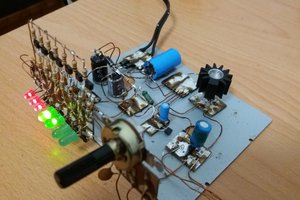
  • Capable of delivering output more 7000V
  • Input Voltage: 12V DC
  • Max input current: 3A
  • PCB Dimension: 73mm x 52mm

The G1 version is a basic implementation of the Mazilli/Royer based ooscillator to drive a flyback transformer. Basically the ZVS(Zero Cross Voltage Switching) circuit topology will allowed the power MOSFET to deliver very efficient power due its switching property at zero voltage crossing between the sine

  • 2 × IRFP250 N-Channel Power Mosfet Discrete Semiconductors / Power Transistors and MOSFETs
  • 2 × 1N4742 12V Zener Diode Discrete Semiconductors / Diodes and Rectifiers
  • 1 × 0.68uF MKP Film Capacitor Safety Film Capacitor
  • 2 × UF4007 Discrete Semiconductors / Diodes and Rectifiers
  • 1 × 47uH 5A Power Inductor Toroidal Power Inuctor

View all 7 components

  • Generated HV Sine Wave

    Azri Jamil07/09/2017 at 03:02 0 comments

    I have setup a HV probe made it myself to check the voltage generated from the flyback transformer and the result is still ambiguous to me. The sine wave is smooth and looks like to good to be true, not sure if I'm missing something in my probing setup. From the oscilloscope reading, the maximum voltage is 7.6kV at almost 34kHz.

    Visually I can see the plasma arc start to arcing around 0.5cm between the brass spark gap, in which I guess the voltage is more than 10kV based on air dielectric breakdown of 30kV/cm (please correct me if I'm wrong).

    Note;

    My poor's man HV probe is using simple resistor divider consist of 10 x 1 MOhm and 1 x 1 kOhm. One tip on the flyback output wire and the ground have been left to touch the table ground.

View project log

Enjoy this project?

Share

Discussions

Similar Projects

Does this project spark your interest?

Become a member to follow this project and never miss any updates