 Doubleyou
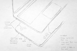
First I opened up the large tile, which contains the default connector and the switch. A quick reverse-engineered schematic of the included PCB helped me to descide how I would modify it with least effort.
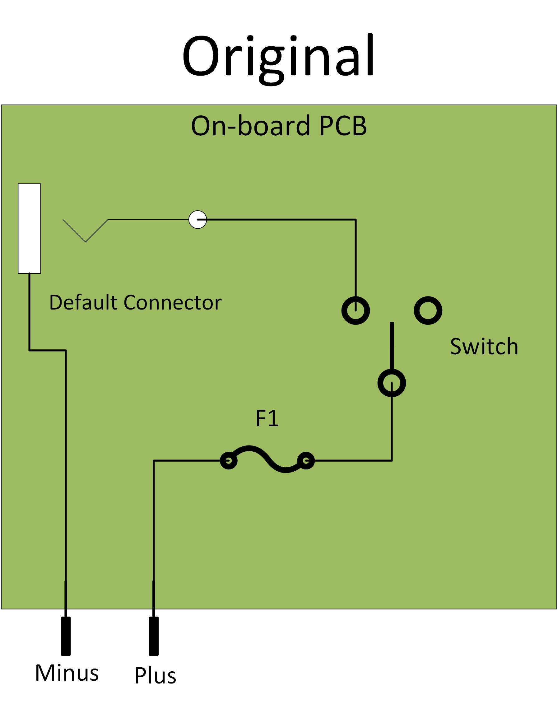
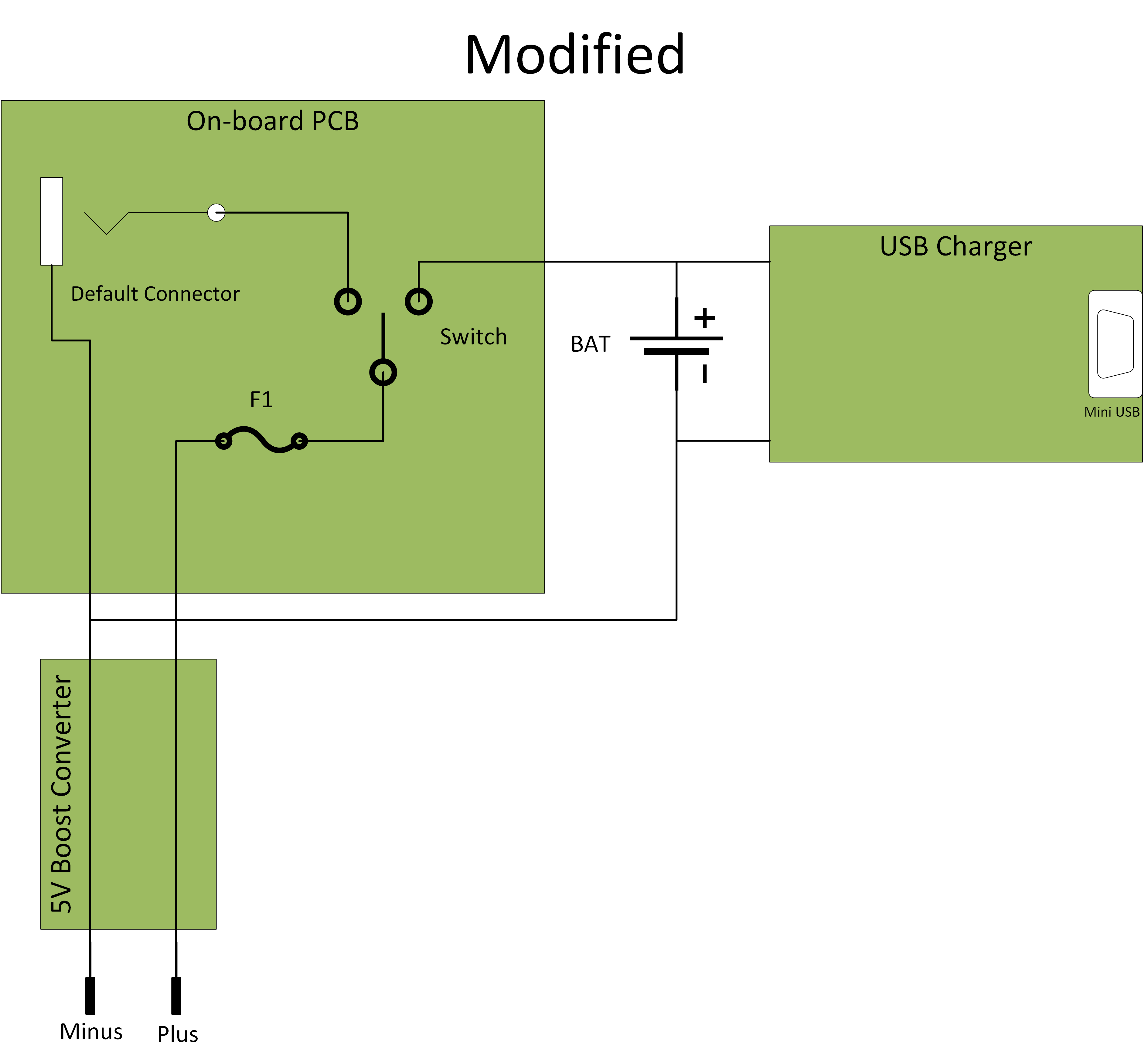
I wanted to use the original electronics as much as possible. After finding out that the switch is SPDT, I decided to add my parts in a way, that the original power supply still works:
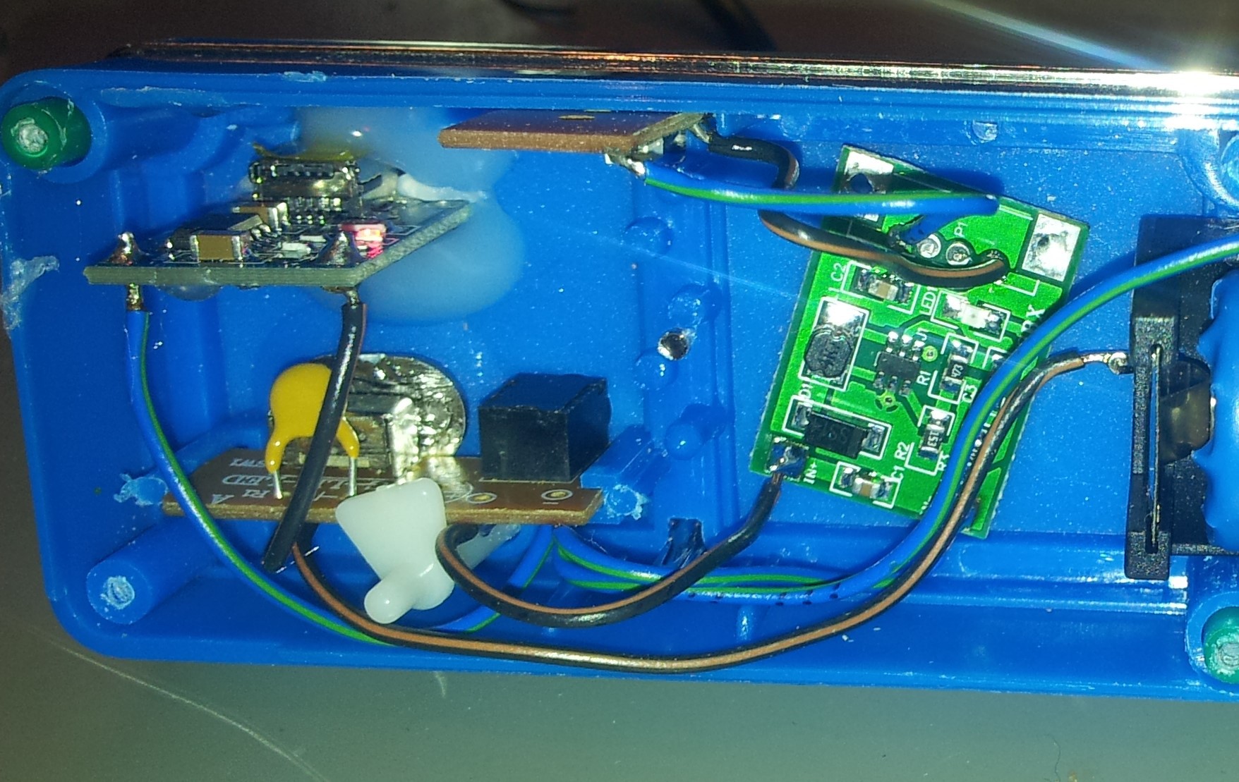
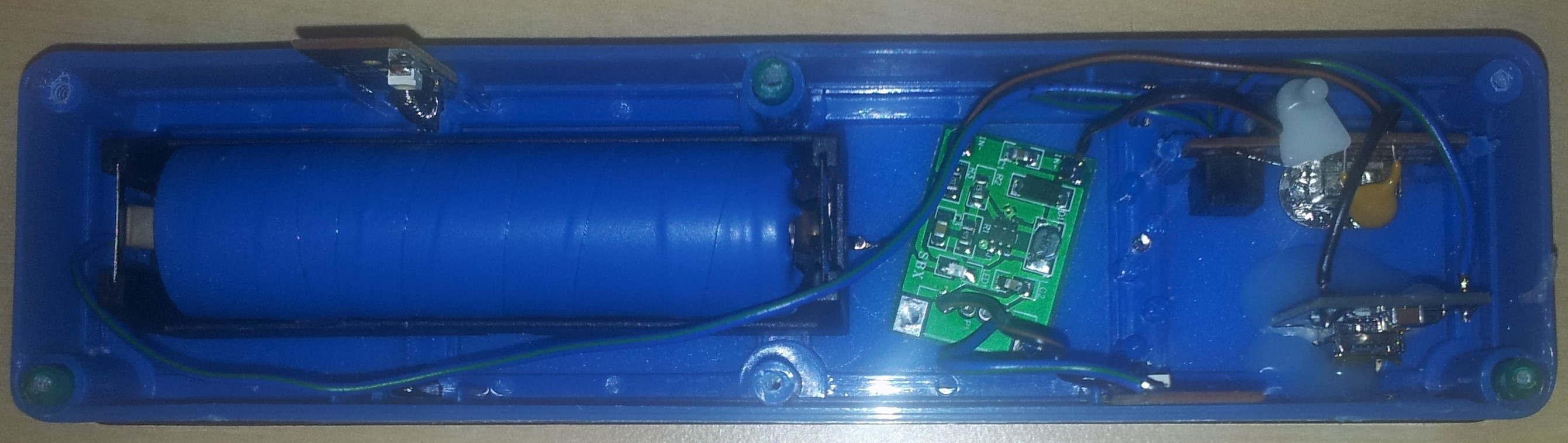
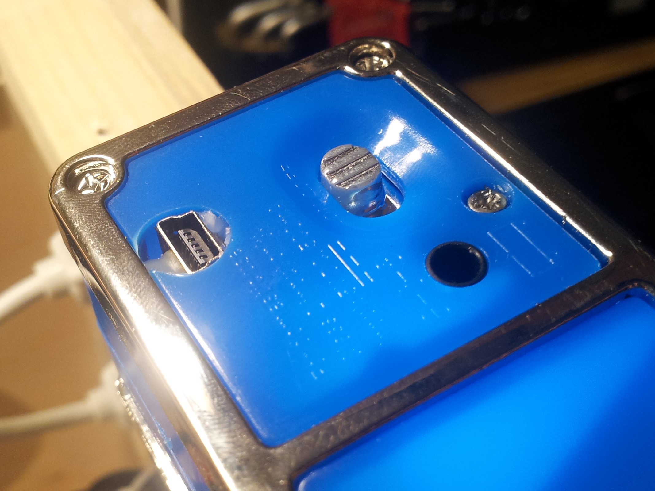
The USB charger and 5V boost controller are cheap aliexpress parts, battery and holder I had lying around. I did not want to spend to much effort and fire up the 3D printer so i just used hot glue to fix the USB charger.
The boost converter originally had a USB connector which I removed because of space limitations. In hindsight I could have used it to use the light as a power bank as well!
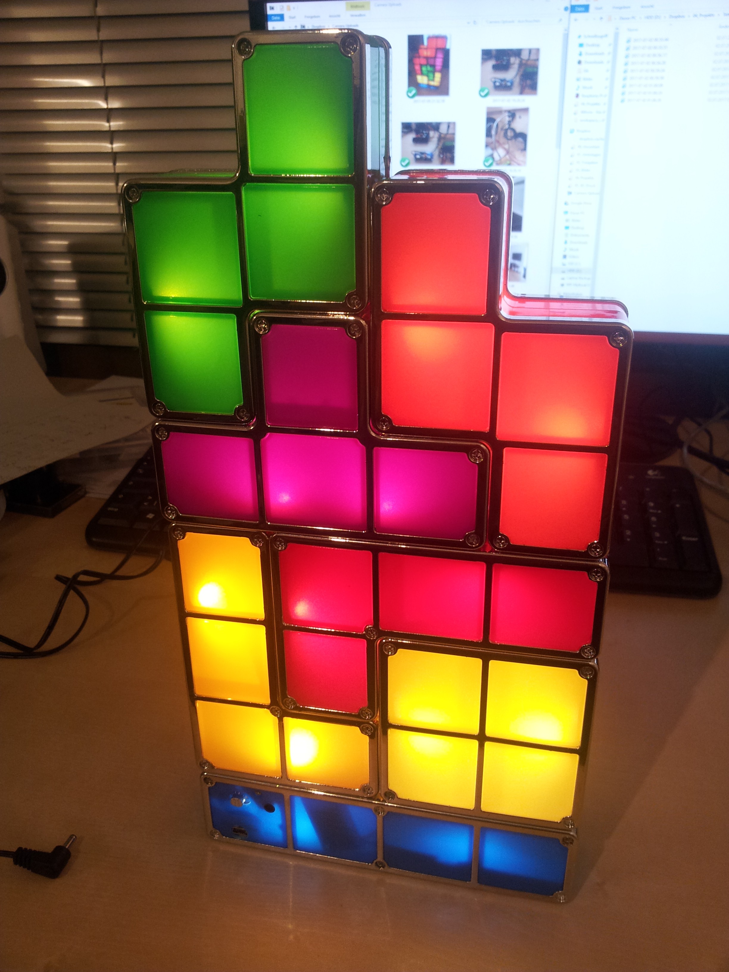
In this configuration, the original 'on' position is still 'on' if the original power supply is connected. The 'off' position is now battery operation. Pluging in the USB will charge the battery.
The result looks like this:
 Harrison Freedman
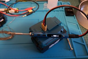
 Tom
Tom
 tobychui
 Beast Devices