Close
0%
0%

Asset Tracker

STM32L433-based board with CAM M8Q concurrent GNSS, EM7180+MPU9250+MS5637 for absolute orientation, and an ESP8285 for wifi connectivity.

Similar projects worth following
This is a small (0.9 x 1.8 in) 4-layer pcb for remote logging of absolute position and orientation.

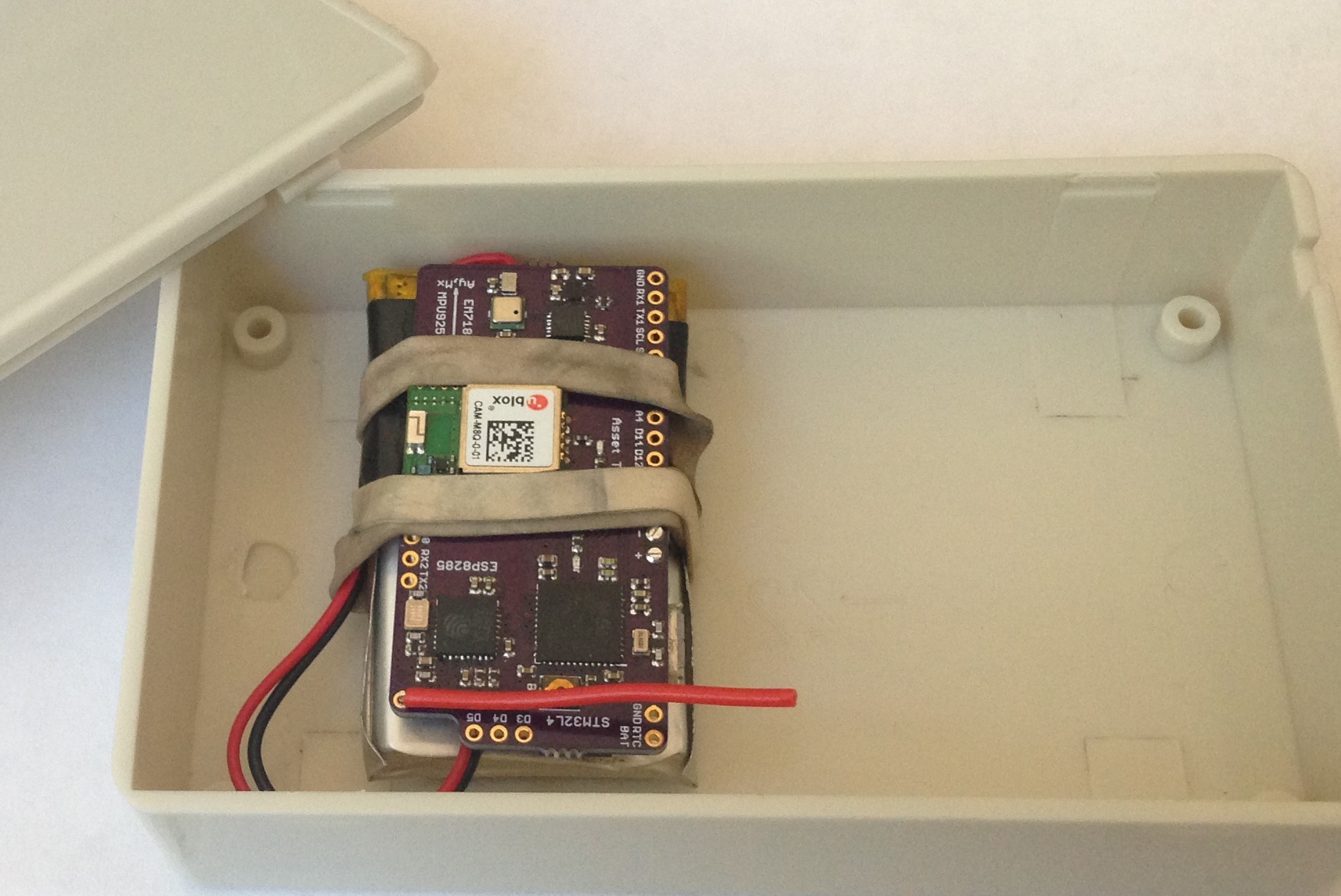
The board uses an STM32L433 Cortex M4F host programmable via the USB connector using the Arduino IDE and an Arduino core created by Thomas Roell.

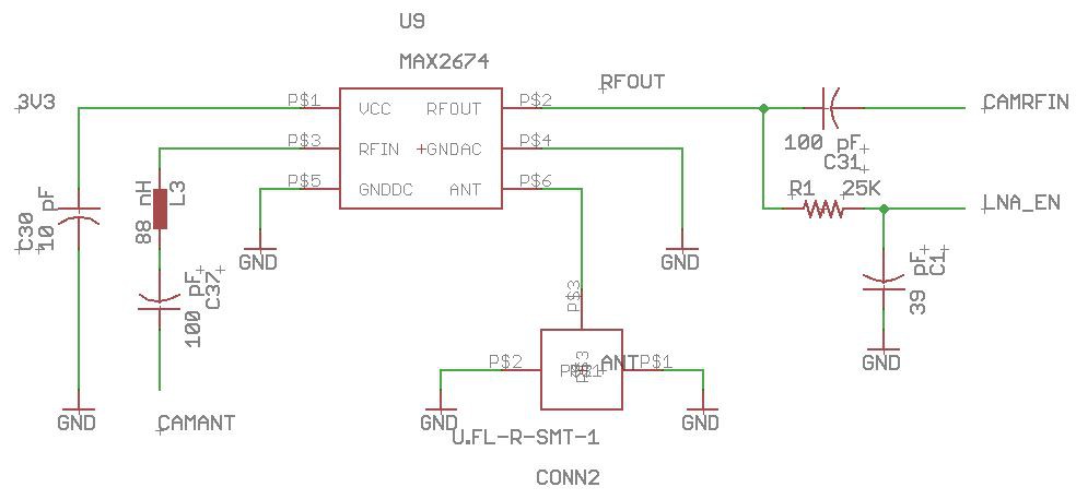
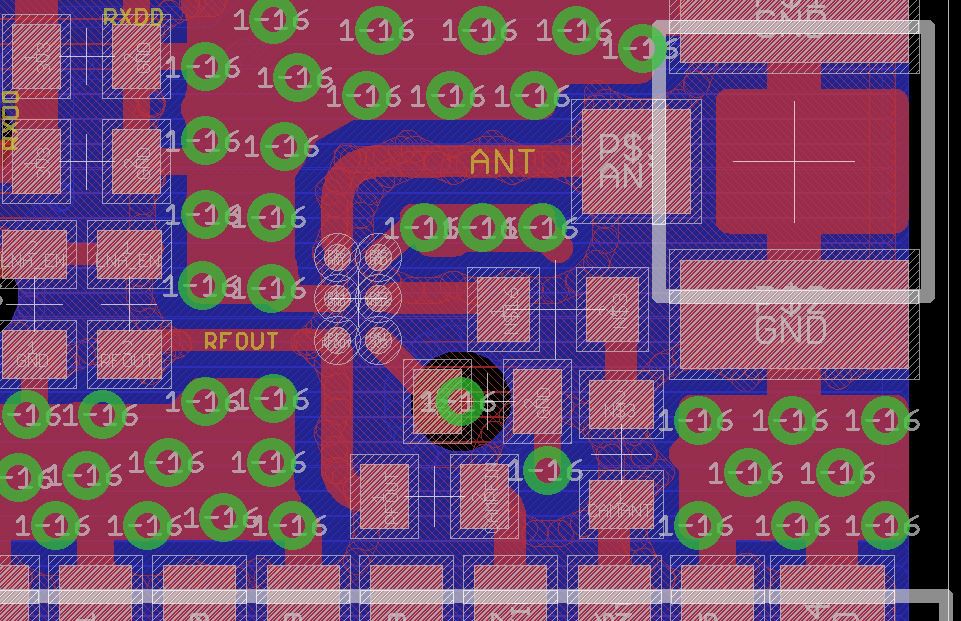
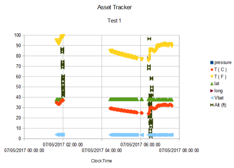
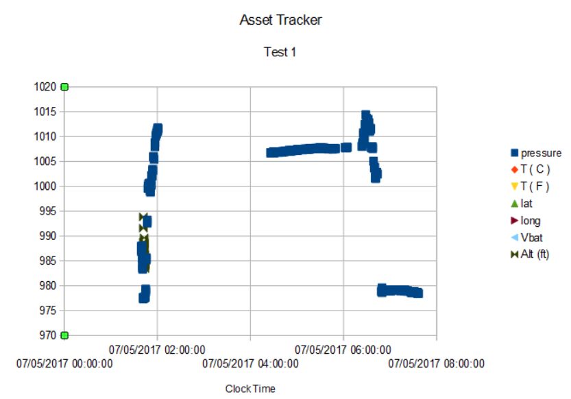
The absolute position engine is a UBLOX CAM M8Q concurrent GNSS module connected to the STM32L433 via UART. The CAM M8Q uses a chip antenna so no external wire or patch antenna is required resulting in a very convenient device package. The pcb is an integral part of the CAM M8Q antenna and the pcb has been sized to meet the minimum ground-plane size recommendations (20 mm x 45 mm).

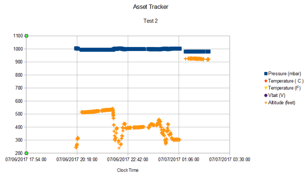
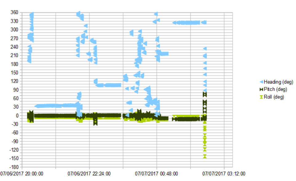
The absolute orientation engine uses the MPU9250 accel/gyro/magnetometer IMU sensor plus the MS5637 barometer as slaves to an EM7180 motion co-processor that sends quaternions and drift-stabilized altitude to the host via I2C.

The EAGLE design files are available on OSH Park shared space.

There is an Arduino library and sketch available on github.

  • Active GNSS Antenna

    Kris Winer10/25/2017 at 18:02 4 comments

    The CAM M8Q is the heart of the Asset Tracker and what a great GNSS engine it is. Even though I am using the minimum recommended pcb board dimensions the chip antenna on the CAM M8Q is really superb. I have been able to track cars around town with little trouble and even get 3D/DGNSS fixes at my workstation indoors, albeit after a ~20 minute wait.

    Still, there are many applications where good enough really isn't, like keeping track of vehicles in a crowded construction site, or when the Asset Tracker is inside of a container, etc. Even in my tests so far, having to wait twenty minutes for a fix is a real power waster. It is best to be able to keep the CAM M8Q on for as short a time as possible to get a fix, and to ask for a fix a very few tmes a day to have any hope of keeping the Asset Tracker going for a year or more on a LiPo battery, which is the project goal.

    For these more practical cases, I need to have a means to increase the sensitivity and what better way than an active antenna. The active antennas themselves are cheap and easy to use, the hard part for this project was figuring out how to allow either use of the chip antenna or an active antenna without having to solder 0 Ohm jumpers or otherwise fuss with the board. With the help of the u-blox forum I found an elegant and effective solution, which I will now describe.

    The solution requires use of an RF switch which also has an embedded LNA (low-noise amplifier) that allows automatic detection and RF path switching when an active antenna is attached but otherwise routes the chip antenna output to the CAM M8Q RF input. There are a few of these switches around, some embedded in SMA connectors; I chose the MAX2674 (actually recommended by u-blox) because it is small, cheap, and easy to use. It is a 2 x 3 WLCSP (SMD wafer-level chipscale package) so some surface mounting experience is required to make use of it. Here is the schematic for the MAX2674 that I used (basically a copy of the reference design, of course):

    There are 100 pF DC blocking capacitors at the CAM M8Q ANT and RFIN pins; in addition, there is a matching 88 nH inductor in series with the DC blocking capacitor for the CAM M8Q chip antenna. I could only find 91 nH inductors but these work just as well. I am not sure how sensitive this choice is but it is a little concerning Maxim chose to specify 88 and not 80 - 100 nH, for example. I will try to find an 88 nH inductor. I have noticed it is often the case that passives are specified in reference designs that can't be found by mere mortals!

    The MAX2674 power pin is bypassed by a 10 pF capacitor. The RF switch and LNA require power, but the MAX2674 also powers the active antenna which can draw quite a few mA, so this adds to the average power usage and somewhat offsets the shorter time to acquire a fix. Lastly, there is a shut down function that can cut power to the MAX2674 to 10 uA. In this design, I have connected the shutdown pin (via a 25 K resistor and 39 pF DC blocking capacitor) to the CAM M8Q LNA_EN pin. The LNA_EN pin is set to HIGH (3V3) when the CAM M8Q is in active mode and is set to LOW (0 V, I added a 100 K pulldown on LNA_EN to be sure) when the CAM M8Q is in power down mode. This ensures the MAX2674 will be powered off (and use 10 uA) even when an active antenna is attached as long as the CAM M8Q itself is sleeping.

    On the Asset Tracker, board space is tight, but this solution requires a very small footprint:

    It's not great to have 90-degree turns in an RF feed but this is the only reasonable way I could find to make this solution work. At the bottom of the image is the CAM M8Q. Left edge in the middle is the shut down passives and LNA_EN connection. The MAX2674 power pin bypass capacitor is between the CAM M8Q ANT and RFIN traces. The active antenna connects to the uFL connector using an uFl-to-SMA cable adapter that can be mounted...

    Read more »

  • More about power consumption

    Kris Winer07/08/2017 at 17:06 0 comments

    07/08/2017

    Test 3 of the Asset Tracker went pretty much the same as Test 2 except I got almost twelve hours of continuous logging but otherwise I see the same kinds of corroborating data along with absolute position from GPS. The one big difference was power consumption. First of all twelve hours is the longest I have gotten the Asset Tracker to run on any LiPo battery, in this case an 850 mAH capacity battery fully charged. But according to the battery voltage data:

    the battery was only down to 4.00 V after the 12 hour run. If I assume a linear drop off to 3.7 V this would mean about 36 hours of run time at an average current of 24 mA. Still much larger (by about 2x) than I expect but much better than the ~50 mA I was measuring when I had neglected to disable the ESP8285.

    I ran another power test with a fully-charged 350 mAH LiPo battery and the Asset Tracker lasted for exactly 20 hours for an average power usage of 17.5 mA; now that is more like it!

    In addition to disabling the ESP8285 I enabled stillness mode on the EM7180, which allows the EM7180 to put its sensors to sleep when it detects no motion. I verified that this works by noting on the TFT display during the test that if I picked up the Asset Tracker or nudged it a bit, the yaw, pitch and roll would respond and keep changing slightly after the nudging stopped, but after a few seconds would freeze to fixed values.

    So for the car logging application I am nearly done. At 17.5 mA average power I can get 48 hours of more or less continuous logging of vehicle (or animal) motion in a small, wearable package. Car tracker, cow tracker, cat tracker...

    And the CAM M8Q is doing what I asked it to do:

    It is taking 5 - 10 seconds of GPS data (I am showing pressure and altitude here but my STM32L432 program only records data if there is a GPS pps pulse--a valid fix--as another low power strategy) every minute like clockwork (twenty minute scale above) with ~1 minute of satellite acquisition and ephemeris update every ten minutes.

    The Asset Tracker + size-matched 850 LiPo battery is about the perfect balance of location/time resolution for fast moving objects (5 - 10 seconds per minute) and power usage (48 hours). But not logging capacity, since 48 hours is only ~3600 out of 65536 pages. Maybe I just need a 1 MByte SPI flash...

    The next class of application is the Sentinel or Security Guard, if you will. In this case, the Asset Tracker needs to acquire a fix once an hour or once every eight hours and report via wifi to a server that all is well. Also, if the Asset Tracker detects that the object is moving it should alert by sending a wifi alarm. In this application 48 hours is not going to do it. If the Asset Tracker can last 48 hours with an 850 mAH LiPo battery updating its location every minute I would hope that it could last, say, 120 days reporting its position every hour and 1440 days every twelve hours, etc.

    In some applications like this, say, monitoring cargo containers at sea, the device reports its location once per day and is expected to remain active for years. Here is an example of 18 months of twice-per-day tracking using an 8800 mAH battery. This is less than the longevity I am projecting with the Asset Tracker. Of course, I haven't factored in the power required by the ESP8285 to send state information/data via wifi, nor have I actually demonstrated this mode of operation, etc. Lot's to do...

    I usually set up a web server to report data via wifi from a remote sensor with an embedded ESP8285 but the web service times out after 30 seconds or so of non-activity and this is not a good match to this kind of infrequent reporting anyway. Better would be an ESP8285 dongle attached to a laptop that can receive UDP messages and store them on its internal 1 MByte flash memory and/or send them on to the serial monitor for continuous observations, like might be done in a plant security control room.

  • First complete test

    Kris Winer07/07/2017 at 18:40 0 comments

    07/07/17

    I am continuing to learn how to get the most out of the Asset Tracker, and I will report on the successful second test below.

    First I want to report that I found out why the average power was measured to be ~50 mA in the initial testing. I forgot that I have pulled up the ESP8285 enable pin with a 12K resistor such that the STM32L432 connected to the ESP8285 enable pin has to set this pin LOW to disable it. So for all of these tests (including the one described here) the ESP8285 was enabled in whatever default mode it comes in as an IC from the factory; I haven't programmed it yet. So I will repeat the average power test with the ESP8285 disabled using the unfairly-maligned 350 mAH LiPo battery and I should expect to get average power usage more like ~10 mA or less.

    For the second test I again took advantage of the test daughter's errands and packaged the Asset Tracker with an 850 mAH LiPo battery partially charged to 4.02 V in a small plastic box like so:

    I was in a rush so the device wasn't "warmed up", meaning it took some time for the CAM M8Q to acquire its first fix, which didn't occur for ~twenty minutes or so after the car left our house. I know this because the first recorded data are at an elevation of 244 feet, which puts the location somewhere in Pleasanton, about 15 miles away from our house.

    This time I obtained a little more than six hours of uninterrupted data, and I recorded absolute orientation data (heading, pitch, and roll) as well as pressure, temperature, time and data, battery voltage as well as latitude and longitude.

    First the GPS position tracking data:

    At this scale it looks impressive but there are several places where the trajectory is clearly not on a road or where there are gaps like here:

    This is mostly due to the 5/60 duty cycle of the GPS periodic mode I chose, and this is a reasonable balance between following the location and conserving power. I can see that the car turned right from Concannon Blvd onto Holmes Street, etc even though some details of the trajectory are missing.

    The goal of the Asset Tracker is to allow tracking over long periods of time. If I can get the average power down to ~1 mA then with the size-matched 850 mAH LiPo battery I could track an object continuously in the above manner for a month.

    The temperature data show the Asset Tracker has no trouble functioning at elevated temperatures:

    The Asset Tracker was placed just under the emergency brake over the drive train and on most cars this space gets pretty hot, especially on a hot July day in Livermore. So it is not surprising the temperature rose to 150 F. Yet, the Asset Tracker had no trouble working and recording data, etc. at that temperature. This is a gratifying testament to the robustness of the design and the hand-assembly of the components on the pcb

    The pressure and pressure-derived altitude show the same elevation changes noted last time that make a nice complement to GPS position data:

    The elevation at ~300 feet is where the car passes Pleasanton at the 580/680 junction, and then at ~500 feet is parked at Livermore. This is the same time that the temperature soars above 100 F so it is not surprising that the elevation estimate creeps up a bit as the temperature rises. The subsequent changes in elevation mark the return through Pleasanton (at ~22:00:00) and entry into the Danville area (elevation ~400 feet). Finally at the end of the trip, the climb up the hill to our house at 1050 feet elevation. Of course, elevation estimated from pressure can easily be off by 100 feet. Altitude provided by GPS can be more accurate but I find too many gaps in the GPS altitude and too much variation to be useful, at least in this driving application.

    The absolute orientation data is interesting as well:

    Since I know that driving times are relatively short in this six-hour record compared to parking times (a fact I could also ascertain by correlating GPS position and heading changes) the more or less constant heading portions of...

    Read more »

  • First practical test of the Asset Tracker

    Kris Winer07/05/2017 at 22:57 0 comments

    July 5, 2017

    Here I describe the first practical test of the Asset Tracker after simply verifying that all of the components (except the ESP8285) work as expected and that pressure, temperature, altitude, latitude, longitude, and yaw, pitch and roll data are properly available to the host and can be written to the 16 MByte SPI NOR flash.

    The flash has 65,536 pages that hold 256 bytes each. I constructed a data packet of 32 bytes such that I can write 8 segments of 32-byte data per page. The 32-bytes is enough for most (but not all) of the interesting information. In this first test, I sacrificed pitch and roll to stay within the 32-byte segment limit. I also chose to write data to the flash every ten seconds. At this rate, the flash can store 90 days worth of data!

    In this first test, the questions I want to answer are simply 1) can I get data logged to the flash and 2) can I meaningfully interpret the data?

    I had previously tested the battery life using a 350 mAH 1S LiPo battery and found even with the ESP8285 disabled (there is an STM32L433 GPIO connected to the ESP8285 enable pin so it should be completely disabled unless I specifically enable it in the code, which I did not so far), the CAM M8Q in periodic mode with a 5/60 duty cycle (seeking a fix for 5 seconds every 60 seconds, in sleep mode otherwise), and the STM32L433 in STOP mode unless servicing quaternion updates from the EM7180 at 10 Hz I could only get about seven hours of life, or an average current usage of ~50 mA.

    The CAM M8Q uses ~25 mA when active so should use ~3 - 4 mA on average in periodic mode. The STM32L433 uses << 20 uA in STOP mode and I chose to set the CPU clock to 4 MHz which similarly saves on power even when the STM32L433 is woken by interrupts and placed back into run mode. The ESP8285 should draw very little power, but I need to verify this. The EM7180 + MPU9250 + MS5637 should require ~10 mA according to separate tests so I am somewhat at a loss to understand how the average power could be anywhere close to 50 mA. This seems much too high to me and I suspect there is something wrong with the battery, like it is only taking a partial charge due to age. Still, six or seven hours is long enough for the first test and I took advantage of the fact that my daughter was heading out the door to go watch fireworks to ask her to drop the asset tracker, placed in a plastic bag inside a mailing envelope with a partial battery charge on her dashboard for the evening...

    The following day I retreived it from her and was pleasantly surprised to find lots of data on the flash. Here is some of what I found:

    There is just over six hours of data but there is a curious two-hour gap, so really only four hours of data. It looks like the data stopped as the temperature rose above 100 F. The daughter reports she had to park the car away from its usual spot and that it was exposed to the setting sun so this could be a case of overheating, although all of the electronics are rated to at least 85 C (max temp shown is ~40 C) so this explanation seems suspect. In any case, the device recovered as the temperature dropped. Perhaps the GPS signal simply skipped two hours, I don't know what to make of this gap. Turns out the Air Force is monkeying with GPS the entire month of July and the gap could be a result.

    Looking at the pressure:

    it is clear that the pressure at first increases as the car descends from the 1050 foot elevation of our house to the relatively lower levels (~300 feet) of the 680 freeway, then spikes as the car crosses the Benicia bridge both at the 02:00:00 and 06:30:00 marks. The bridge is just ~100 feet above sea level. All during the experiment the pressure is slowly but steadily rising. Upon return home, the pressure is higher by a few mbar.

    Perhaps surprising compared to the absolute positioning afforded by GPS and absolute orientation afforded by the EM7180 (which data I have not yet analyzed for this experiment), lowly pressure data holds a lot of information...

    Read more »

View all 4 project logs

Enjoy this project?

Share

Discussions

yasemin elfida wrote 06/13/2018 at 10:17 point

Hallo Chris, what a great project! I am studying medical engineering and I have a test project with a MPU9250 in combination with the SENtral EM7180. In my case the SENtral can not become Magnetometer data. The function: "void readSENtralMagData(int16_t * destination)„ delivers no data, just 0 for mx, my ans mz. What can I do to avoid this? What is the correct way to become Magnetometer data from the EM7180?

  Are you sure? yes | no

nick shrake wrote 08/11/2017 at 19:06 point

Excellent project Kris.  I made a similar effort a few years back with a design that I scrapped due to too high power consumption and inability to get my Antenova GPS chip antenna to lock.  Wise to get an integrated module, if I repeated I would pursue that path.

Curious, have you heard of OpenGTS?  It's an OSS server application using Apache Ant that client sensors to push GPS and metadata.  Might make for a nice addition in as you could dump the results over EPS WiFi over TCP or HTTP socket.  

Link below:

http://www.opengts.org/

For MPU9250 are you intending to implement custom sensor fusion or use their DMP 

Embedded MotionDriver 6.12 blob?

Keep up the good work! 

- Nick

  Are you sure? yes | no

Kris Winer wrote 08/11/2017 at 19:14 point

Hi Nick,

I have a version of the Asset Tracker sitting on my workbench that uses a Murata LoRa module instead of the STM32L433 + ESP8285. I am just waiting for the completion of the STM32L082 Arduino core to put it into use. As part of these efforts we use some kind of gateway to get the data to the laptop. UDP and an ESP8285 dongle for ESP8285 wifi, an nRF52 BLE dongle for the nRF52 (from an early version of the Asset Tracker), and TBD for LoRa, but probably something that looks like a laptop dongle.

As far as the MPU9250, neither. Although we have both open-source Magdwick and Mahony filters available and in use we rely on the EM7180 motion co-processor to manage the sensors (both MPU9250 and MS5637) and do the fusion filtering including Euler angles as well as drift-compensated altitude. You can read more about this here:

https://github.com/kriswiner/EM7180_SENtral_sensor_hub/wiki

  Are you sure? yes | no

Kris Winer wrote 07/06/2017 at 02:25 point

Thanks! It's been a lot of fun, and the fun is just beginning now that I can start applying it to tracking real assets. Is a cat an asset or a liability?

  Are you sure? yes | no

oshpark wrote 07/06/2017 at 02:22 point

Great project!

  Are you sure? yes | no

Similar Projects

Does this project spark your interest?

Become a member to follow this project and never miss any updates