 doctek
My Perfect Purple PCBs showed up a few days ago, so it was time to build and bring up the boards. (OK. It's really been a few weeks ago. Never claimed I was quick.) I cut the solder paste stencil using my Silhouette Portrait and 3.5 mil overhead transparency film (mylar). Cleaning the chad out of the stencil holes took a bit of effort, especially on the tiny holes for the accelerometer. I broke one of the spaces between the holes, but thought it would be OK to have a tiny bit of extra solder paste. Reflowed in my toaster oven and began check-out.
Looking at the board, I noted that the accelerometer was skewed - both twisted and tilted.
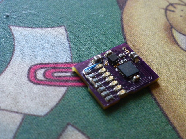
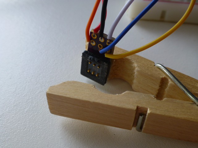
Looked like that extra solder paste came back to bite me! I proceeded with check out any way. Power and ground were not shorted! That's always a relief. But then things got interesting. To check out anything more, I needed to program the ATTINY84. It was time to build at least one of the uProgrammers. I chose the 2x3 version since the pads on the POV board were larger. Here is the uProgrammer mounted to the exotic clip I fashioned to hold the programmer in place. Worked fine.
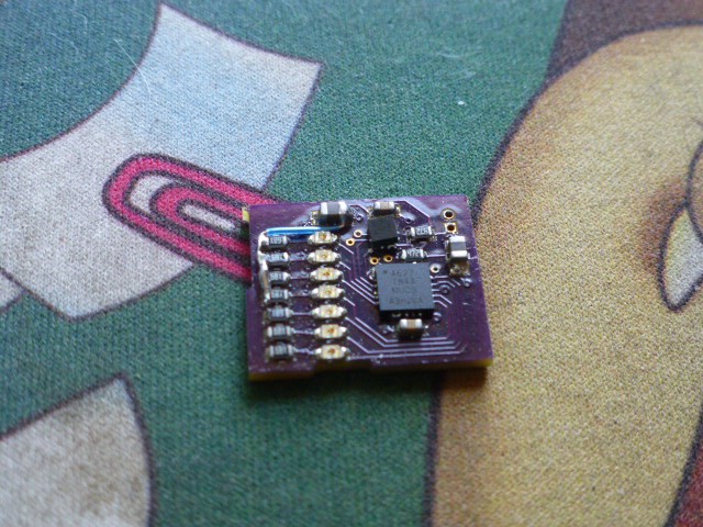
In the process of checking the board, I looked closely at the board design in KiCad and noticed to my dismay that I had left a section of ground plane floating free. You'll notice the bit of blue wire on the board to fix that. The problem happened when I added the uProgrammer positioning notches. Fortunately, the fix was easy. I fixed this before I did any other board testing.
In short order, I established that the contactor and spacer used for the uProgrammer had continuity. The signal paths from the wires on the uProgrammer to the POV board tested solid. But there was at least one obvious problem. The MOSI line should have shown a 4.7K resistance to Vcc, but instead was shorted. Checking the accelerometer footprint, Vcc and MOSI were next to each other in the corner that had the extra solder paste. Uh-oh! The only way I could think of to clear the short was to use my hot plate and unsolder the accelerometer. I did that and the short was obvious. I used my soldering iron to remove the extra solder paste and clear the short, but I haven't put the accelerometer back on yet. Lots I could test without that complication for now.
Moving ahead, I verified that the programming signals (Vcc and ground, MOSI, Reset,and SCLK) all looked good. But the part wouldn't program and MISO clearly was not sending the correct levels back. What could be wrong? I didn't know. After pondering the situation a while, I decided to take a look at the signals while programming the DIP version of the ATTINY84. Of course, these looked fine, so the next step was to try to mess them up and see if I could get MISO to look like what I saw on the POV. Disconnecting MISO was a possible, but I thought that might be too easy. Disconnecting VCC was another way, and this seemed more plausible - especially when I looked carefully at the pads around the ATTINY84. It appeared that the Vcc pad did not have any paste on it. I made the pad-to-pin connection with a pin point and got Blink to program! So I knew this was the problem. A little work with a very tiny soldering tip, a bit of paste and some liquid flux, and the joint looked better and the ATTINY84 programmed! On to developing the POV program.
Discussions
Become a Hackaday.io Member
Create an account to leave a comment. Already have an account? Log In.