 doctek
Soon, I will add a complete parts list, but I intend to provide Digikey links and that will take some time to put together. For now, it's perhaps helpful to say the accelerometer I'm using is the LIS2DE12 by ST. It's tiny (2mm square), cheap (< $2 in onesies), and has an easy I2C interface. Three tasks seemed reasonable for the accelerometer: Turn on the Fidget POV when I want to play with it, put it to sleep when I'm done, and stabilize the display of the text. (This last task is one I didn't anticipate until I actually put up the first letters. When I saw how they jumped around, I realized that stabilization was necessary!) Easy enough, I thought. But I soon discovered that accelerometers are not intuitively understood devices, at least not by me. What I will discuss in the following took me almost a month to figure out. I'll try to spare you all the sordid details, but still hit the key points.
My initial assumptions included:
- radial acceleration due to rotation was small - less than 1G.
- tangential acceleration due to rotation was negligible.
- the positive directions for sensing were as shown in the accelerometer data sheet.
Based on these assumptions, I selected the +/-2G scale and expected mostly positive values of acceleration. But nothing worked as I expected! So I had to do some testing. (Those last two sentences took a couple of weeks of experimenting!) There was no easy way to read out exact values of acceleration. Storing values in EEPROM and reading them back with avrdude was considered, but I couldn't figure out how to start gathering data at an "interesting" point. Then I realized that I could use the leds to indicate acceleration levels! Turned out to be a great idea and guided me to an understanding of the accelerometer. For anyone who would like to repeat my experiments, have a look at T84_POV_Test_Accel_Max.ino. You should be able to easily see where to change the accelerometer configuration (mainly the range) and how to adjust which axis and what values light the various leds. The accelerometer returns an eight bit result for each axis in two's compliment form. Since this is just what C uses as a signed number, no further manipulation is required. Just remember you're dealing with a signed number when you do comparisons.
To reach a workable level of understanding of the accelerometer, I also had to think carefully about exactly how the accelerations acted on it. The figure below shows the accelerations that act on the POV as it rotates, at four points in a rotation.
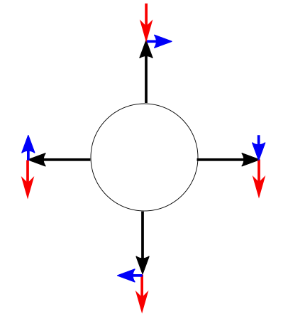
The black arrow is the radial acceleration, the blue arrow is the tangential acceleration, and the red arrow is gravity.
Skipping a lot of confusing experiments, here's the results:
- radial acceleration due to rotation is large - exceeding 16Gs if spun very hard. And it's in the negative y direction. Rotation must be nearly stopped before the rotational acceleration drops below 2Gs.
- tangential acceleration is small - less than 1G mostly - but not negligible.
- the positive axes directions for x an y are opposite those shown on the data sheet.
You can see that my assumptions were completely wrong! Convincing myself that my results were correct was probably the hardest part. The following figure shows the orientation of the accelerometer at four points in one rotation.
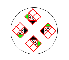
The positive sense directions are shown as the colored triangles. Comparing this to the figure above showing the accelerations acting on the POV, we can conclude that acceleration along y will always be large (like maximum negative value kind of large) and negative until the rotation is nearly stopped. So all control needs to be done with x values. The x values stay within +/-4Gs. Fortunately, that works great and results in a stable display of the POV text.
Discussions
Become a Hackaday.io Member
Create an account to leave a comment. Already have an account? Log In.