 paulusjacobus
My journey with the Arduino PCB's began a year ago when I purchased Chinese K40 Laser cutter and engraver from eBay which I upgraded with a Grbl controller based on the UNO R4. After experimenting with a stock Arduino UNO R3, I decided that I needed a better Arduino with at least one additional 16 bits PWM channel without an added price tag. Since I am controlling a CO2 laser, speed or additional processing power are not a requirement since the CO2 gas needs time to ionize and quality engraving takes time. Throwing in a huge ARM processor on 80MHz is not going to make a huge difference. Since the stock laser beam is 0.15 mm wide, a better focusing lens or lower power (slower movement) to reduce the beams width would help. Of course you can buy existing upgrades now but they weren't available a year ago when I got my K40. For those interested, here is my kickstarter. My latest Kickstarter uses a STM32 (super Gerbil see here Super Gerbil.
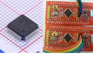
I did find a good candidate in the 328PB which is a more powerful sibling processor because of its extended features (additional ports, two additional 16bit timers, 2 USART’s) and it’s actually cheaper as well.
| Atmega328PB | Atmega328 |
| Unique Device ID | - |
| 2* Serial Interface | 1* Serial Interface |
| 2* SPI | 1* SPI |
| 2* I²C/TWI | 1* I²C/TWI |
| 27* Digital IO | 23* Digital IO |
| 3* 16Bit Timer | 1* 16Bit Timer |
| 10 PWM Channel (PD2 double used) | 6 PWM Channel |
| Clock Failure Detection | - |
| Waveform Generator | - |
| USART Sleep Mode Wake up | - |
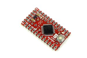
Since I could not find any new Arduino boards based on the 328PB, I decided to make my own R4 based on a R3 board. My first attempt was using a stock Arduino board and carefully removing its current Atmega 328 processor and soldering in a new advanced Atmega 328PB. Unfortunately, it did not work so I had a second attempt with another board which failed as well. I could program it but that was it, no ‘hello’ life sign from Grbl when starting it up. After carefully reading the Datasheet, I discovered that the manufacturer removed the so-called ‘full swing oscillator’ clock circuit in order to make room for the additional features and that the chip needed a high performance crystal rather than the cheap crystals or RC based circuits that are being utilized in the current clone Arduino boards. So I made a board for the 328PB but first the software hack before we jump into that.
The Grbl changes.
To make this work we need access to an additional 16 bits Timer so we can do detailed engraving. I had a TMR3 and TMR4 available but both share the UART0 port pins that does the comms with the G-code sender. So the hack here is to move that port from UART0 to UART1 and reroute the USB interface. I did put in two circuit jumpers so I can swap the port easily around and allows me to use OPTIBOOT see here
In Grbl firmware, we need to look up the UART registers and replace the -0 indicator with -1, simple. i.e. UDRE1, USART1 etc. I have posted the Grbl converted firmware on my Github (please do check the code)
USART1_RX_vect, USART1_UDRE_vect (see cpu_map.h and serial.c)
Next thing is moving the PWM output from Port 2 to Port 4 and configure it.
| #define PWM_MAX_VALUE 653534.0 | |
| #define TCCRA_REGISTER TCCR4A | |
| #define TCCRB_REGISTER TCCR4B | |
| #define OCR_REGISTER OCR4A // Top value Use Channel B for PWM output! PWM Channel B is tied to Dig Pin 10 | |
| //Timer 2 to timer 4 conversion. COM1A1 was set for Dig Pin 11 Channel A | |
| // #define COMB0_BIT COM4A0 | |
| #define COMB_BIT COM4A1 //uses channel B dig pin 10 while channel A is dig pin 9 | |
| #define WAVE0_REGISTER WGM40 | |
| #define WAVE1_REGISTER WGM41 | |
| #define WAVE2_REGISTER WGM42 | |
| #define WAVE3_REGISTER WGM43 |
Here we assign Pin 1 to the PWM output.
#define SPINDLE_PWM_BIT1// Uno Digital Pin 1 - PD1 OC4A
Next step is to convert the pwm spindle parameter from 8 to 16 bits. (spindle_control.c)
| #ifdef CPU_MAP_ATMEGA328PB //uno R4 Channel A -> COMA, PD1 port used OC4A | |
| TCCRA_REGISTER = (1<<COMB_BIT) | (1<<WAVE1_REGISTER) | (1<<WAVE0_REGISTER); | |
| TCCRB_REGISTER = (TCCRB_REGISTER... |


 Sandeep Patil
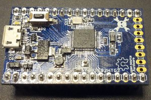
 Michele Perla
 Sander van de Bor
Here is one of my recent blogs about replacing the legacy hardware on the lasers and CNC machines... https://awesome.tech/xt-computers-4-cnc-machining-really/