Close
0%
0%

Bluetooth Speaker System with Powerful Bass

A portable, high power subwoofer and speaker with custom passive radiators that can connect to and sync with 5 external Bluetooth speakers.

Similar projects worth following

Overview

Common shortcomings of portable Bluetooth speakers on the market include uninspiring bass and the inability to fill a room with sound. Our aim is to design a portable Bluetooth speaker with powerful bass that can sync with several other Bluetooth speakers. There are tons of Bluetooth speakers available of varying price and quality, but few with good frequency response below 100Hz. Most support connection with a single phone or computer, but few are capable of more than that. We haven’t been able to find a single one that combines this connectivity, portability, and low base at a reasonable price, so we decided to make our own.

Designing a speaker that improves on these features will be a major challenge. Specifically, designing an optimal enclosure with custom passive radiators, and enabling Bluetooth connectivity with several speakers will be the most difficult (and interesting) aspects of the project. The end result will be a unique speaker that can be used as the main hub for a conveniently portable system.

We are a small startup based in San Francisco called Podo Labs Inc., focused on creating well designed hardware products. Developing this project into a manufacturable speaker (and selling it) is the end goal, but we hope that by making available our research and prototyping steps, we will both inspire people getting into DIY speaker design and elicit feedback from the community.

Notes

A Bluetooth Developer License from Qualcomm is required to exactly replicate the speaker, although we will provide suggestions about how to work around this with off the shelf components.

View all 11 components

  • Making the Speaker Part 3: Connectivity

    Sam Pullman07/24/2017 at 10:46 3 comments

    As far as connectivity is concerned, the most common speakers on the market fall under three categories:

    1. Wired - Usually ¼ or ⅛ inch stereo jacks, or RCA
    2. WiFi - Allow syncing between speakers connected to the same WAP, usually a non-portable system
    3. Bluetooth - Common in portable speakers, these allow direct streaming from a phone/PC/etc

    We are interested in both portability and syncing multiple speakers. WiFi systems (such as Sonos) connect to your home router and have some sort of phone/computer interface for setup and streaming. That won’t work for us, because we don’t want to bring a router to the pool/beach/park. Technically it may be possible to create a speaker that serves as the access point that others connect to, but the resulting complexity and trade offs, along with the fact that there is a large selection of Bluetooth speakers available that many people own already, dictated we go with Bluetooth as our connection method.

    Current Bluetooth speakers generally allow streaming from one source at a time, and not much else. Fortunately, some unique capabilities of the Bluetooth IC we’re using (CSR8670) presents us with a few options. Without too much work, it supports “sharing” a synchronized audio stream with a second CSR chip. This is perfect for a 2 speaker setup, and it is what we have implemented in our prototype.

        Shown: Prototype with amp, battery, driver (only woofer here, no full range or tweeters). Two Bluetooth modules are connected and synced, audio source is the phone. The blue thing on the left is a cheap battery powered speaker.

    The two obvious drawbacks to this approach are that the system is limited to 2 speakers, and that the second speaker must have a CSR chip. Many Bluetooth speakers do either use a CSR645, CSR8670, or earlier variant, but in any case we are still stuck with a maximum of 2. After considering several options to overcome this hurdle, we have decided to pursue an unorthodox solution. To meet the goal of connecting 6 speakers (including ours) we will add 2 more CSR8670 chips. The first chip will perform the same function as our current prototype, but also will output two PCM streams to the other CSR8670s using I2S. They will each be able to stream to two external speakers, which the CSR8670 is capable of doing when using a non-Bluetooth audio source. To help visualize the setup, see the below diagram.

    A somewhat non-obvious issue with this configuration is dealing with Bluetooth audio latency. The speaker should be capable of connecting to any other Bluetooth speaker, but there is no standardized way in the Bluetooth A2DP spec of synchronizing this sort of arrangement. Since Bluetooth audio latency can range from 30ms to 200ms+, naively streaming to 5 other speakers is unlikely to sound good. A mismatch of 20-30ms or so is probably the upper limit of acceptable, so one speaker playing with 50ms latency and another with 180ms is problematic.  The strategy we have come up with is to:

    • Delay the speaker output 200ms when connected to external speakers
    • Delay external speakers 100ms by default
    • Implement manual controls for increasing/decreasing the delay for each external speaker in 10ms increments
    • Remember previous delay for each paired speaker and use as default

    The manual controls will be implemented in an Android/iPhone app, using CSR’s (Qualcomm) GAIA protocol. Due to NDA restrictions we can’t go into too much detail about how this is done, but you can view a high level explanation of GAIA here. The

    We will work on this strategy over the next few weeks, and periodically log our progress.

  • Making the Speaker Part 2: Construction

    Sam Pullman07/24/2017 at 10:44 0 comments

    Introduction

    In this log, we will detail how we built and tested our initial functional prototype.

    Processes

    Our first step was to find rubber samples and set up a test enclosure. We acquired two types of rubber (neoprene and natural latex) in a variety of thicknesses (1/16in to 1/4in) and hardnesses form CAL NEVA Supply Co. Rubber hardness is measured by the Shore Durometer scale. We got rubber samples ranging from 20A to 50A (about rubber band to pencil eraser hardness).

    Image result for shore durometer scale

    Image Source: https://albrightsilicone.com/a-guide-to-shore-durometers/

    We found a local shop that specializes in cutting rubber into gaskets. They were kind enough cut out some sample radiators with their awesome CNC reciprocating knife. They said we were their first customer to ever use rubber to make sound rather than dampen it.

    At the local hackerspace Ace Monster Toys I cut out a test enclosure with the CNC router. I designed the enclosure to make it easy to switch out different passive radiators.

    I also super glued up a few test radiators using some of the rubber samples and metal dishes. The metal dish is actually a ladle holder from Daiso. We ended up clearing out three different Daisos for their ladle holders!

    Experiments

    The goal of our experimentation is to characterize the DIY passive radiators made from various types of rubber. Then, we will input this data into speaker design software (WINISD Pro or BassBox6) to see if they can be tuned to extend the bass response of our enclosure. Finally, we must verify the computer simulations.

    Equipment used:

    To fully model a passive radiator the following parameters must be determined:

    • Cms –  mechanical springiness of the rubber
    • Mms – moving mass of the radiator
    • Rms – mechanical resistance of rubber
    • Sd – diameter of the radiators

    Notice that the first two terms are the same terms needed to determine the resonant frequency of a damped harmonic oscillator. We will use this fact to characterize the passive radiator.

    Procedure:

    • Plot impedance curve
    • Measure resonant frequency
    • Add known weight
    • Plot impedance curve
    • Calculate Cms from change in resonant frequency
    • Use Cms Mms and Sd to model driver
    • Guess and check Rms (by comparing to impedance curve)
    • Use software to tune subwoofer for bass extension
    • Verify software tuning

    The above image shows the test setup for measuring the free air resonance of our driver. The HP 3562A dynamic signal analyzer sweeps frequency across the the driver and a 1K series a resistor. Simultaneously, it measures the voltage across the resistor and the driver to derive the impedance. For more details, see this PDF https://www.bksv.com/media/doc/bo0202.pdf

    Above is our hexagonal test enclosure next to a scale and modeling clay. The modeling clay can be added onto the passive radiators inside the enclosure to tune their resonant frequency.

    The next log will discuss the connectivity side of things. After that, we will log the speaker experimentation process in further detail, as well as describe the results of our analysis.

  • Making the Speaker Part 1: Theory

    johnfitzeecs07/24/2017 at 09:23 0 comments

    Introduction

    There are two main steps in building a speaker that sounds good: choosing the right driver and designing an optimal enclosure. There are tradeoffs to consider in both steps, including loudness, bass response, size, weight, cost, and many more. Our goal is to make the best speaker possible while allowing for portability, and keeping cost at a reasonable level.

    Before going on to the actual prototyping and experimenting, it will be helpful to explain some of the theory behind speakers and subwoofer enclosures. In this log we will discuss our research into the theory of speaker design.

    Speakers

    Speakers are electrical, mechanical, and acoustic devices, meaning they transduce electrical energy into mechanical vibration, which in turn creates air pressure waves (sound). The mathematics behind this transformation can be described by a set of physical specifications known as the Thiele and Small parameters. These parameters are named after a pair of professors who pioneered the electric-acoustic modeling of speaker enclosures.

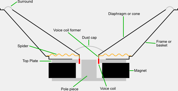
    Breakdown of a speaker. Source: https://en.wikipedia.org/wiki/File:Speaker-cross-section.svg

    Basically, a speaker can be described as a sort of damped harmonic oscillator. Or in other words, the mass hanging from the end of a spring. The Thiele and Small parameters relate the speakers to this mass spring system. Both the speaker and the mass/spring will have a natural resonant frequency.

    For a more in depth resource on the topic, see: https://en.wikibooks.org/wiki/Engineering_Acoustics

    Image result for damped mass oscillator

    Image source: http://hyperphysics.phy-astr.gsu.edu/hbase/oscda.html

    Enclosures

    Why do speakers need enclosures? Well, when the diaphragm of a speaker pushes forward, it generates positive pressure in front of it and negative pressure behind it. Without an enclosure the pressure waves will fan-out around the speaker and cancel themselves out.Image result for speaker pressure waves without enclosure

        Image source: https://soundphysics.ius.edu/?page_id=1343

    The simplest type of enclosure is a sealed enclosure, which completely encloses the back side of the speaker and stops the backwards generated waves from escaping. More complex designs, such as ported enclosures, allow some of these backward waves to reinforce the forward waveform, thereby making the speaker louder. If the system is properly tuned (just like a damped harmonic oscillator) it can even help the speaker produce lower frequencies.

    There are many varieties of ported enclosures, the most common being a bass-reflex or vented system, in which a hole (or vent) is cut into the cabinet.  A passive radiator design exhibits similar properties as a bass-reflex system, but has a few benefits that fit well with our goals. It requires less volume, is closed off to the outside, and is easier to tune. Instead of cutting a new hole (or making a new enclosure) as is required to tune a vented design, you can simply add or remove mass from the passive radiator. The lack of  a hole also makes it much simpler to protect the electronics and driver when used outside.

    File:Passive radiator enclosure.svg

    Image source: https://en.wikipedia.org/wiki/File:Passive_radiator_enclosure.svg

    Back in Thiele and Small's days the frequency response of this speaker/enclosure system would be determined by comparing it to set of precomputed response (or "Alignments"). Nowadays, speaker modeling software allows one to quickly compute the frequency response for changes to the enclosure (e.g. adding weight to the passive radiators).

    Image result for speaker pressure waves without enclosure

    For electrical engineers like myself, can be helpful to view the transformation of electricity into acoustic energy for a passive radiator speaker enclosure as the following circuit (Warning - PDF).

    jahonen.kapsi.fi/Audio/Papers/enclosuremodelling.pdf

    One thing to note is that resonance of the speaker (and that of the passive radiator) will show up as electrical impedance maximums or minimums at the input to the speaker. This gives us a simple method to experimentally determine the resonant frequency of our DIY passive radiators (and...

    Read more »

  • Planning the Speaker

    Sam Pullman07/24/2017 at 06:27 0 comments

    Prototyping

    To validate independent aspects of the design concurrently, we will work on two separate prototypes in parallel. The “works like” model (or in this case, “sounds like”) will focus on the functional aspects of the speaker, while the “looks like” model will explore options for the look and feel of the final product. They are not completely independent, though. While building the “works like” we will keep in mind size, weight, and cost limitations. The “looks like” prototype will be similarly constrained once we have an idea of the physical dimensions of the components (speaker driver, battery, ideal enclosure volume, etc.)

    Given the overall project goals, we came up with a decent starting point for the speaker’s characteristics. The main driver will be a (sub)woofer targeting 5 inches in diameter, with maximum power of 40 - 70 watts, and free air resonance (Fs) around 50-60Hz (there are other important parameters which we will discuss in a later post). Depending on the final choice of driver, the frequency response will be cut off below 20Hz and above 500-1000Hz. Two approximately 15 watt full range drivers will ensure highs are sufficiently represented. We feel this is a good starting point for balancing portability, sound quality, and bass response.

    Works Like

    Development of the functional prototype will consist of testing different speaker drivers, calculating optimal enclosure parameters, and experimenting with different driver/enclosure combinations. For reasons which will be explained in the next log, the enclosure will be a passive radiator system. In order to iterate quickly the following general procedure will be used:

    • Order sample drivers with stated parameters that best match our criteria (via Parts Express or directly from driver manufacturers)
    • Use BassBox Pro and hand-calculations to determine ideal enclosure size
    • Build an enclosure from particle board (using off the shelf rubber and ladle stands from our local Daiso for the passive radiators)
    • Measure the frequency response and adjust by adding clay to the ladle stands on the passive radiators
    • Using what we’ve learned, repeat until satisfied

    We will use off the shelf components in the initial prototype for most of the electronics, which will allow us to focus most of our efforts on the enclosure. A few RC car batteries in series should work well for powering the system, and a 100W Class D amplifier board from Amazon will suit our purposes. The amplifier board uses a TDA7498 IC from STMicroelectronics, which is a good candidate for the amplifier circuit once we move to production. Since the board already has RCA input, not much is required for basic playback except an RCA/Aux adapter.

    For wireless connectivity we will use a custom PCBA with a CSR8760 chip, which was developed for another ongoing project of ours called Jack. CSR8670 modules can also be found on Amazon, eBay, Aliexpress, etc. In addition to streaming Bluetooth audio, the chip has a fairly advanced DSP that can handle crossover for the system. It also has touch sensor and GPIO inputs for the external buttons. Unfortunately, a development license for CSR (now owned by Qualcomm) chips is about $3000 USD, so it’s probably a no go for one off projects. A better solution for DIY projects would be to use a separate crossover board and Bluetooth module, which are widely available on Amazon, parts-express.com, and many other sites.

    Looks like

    Finding the right aesthetic and mechanical features is very important, and can be worked on separately from the functional prototype. Some aspects of the final mechanical design are dependent on the result of the functional prototype, such as enclosure volume and external interfaces (buttons, chargers, wired audio connectors, etc.). We chose a spherical enclosure to highlight the passive radiators, to encourage omnidirectional sound, and for its unique look.

    The first step is to come up with a preliminary...

    Read more »

View all 4 project logs

Enjoy this project?

Share

Discussions

Similar Projects

Does this project spark your interest?

Become a member to follow this project and never miss any updates