 matseng
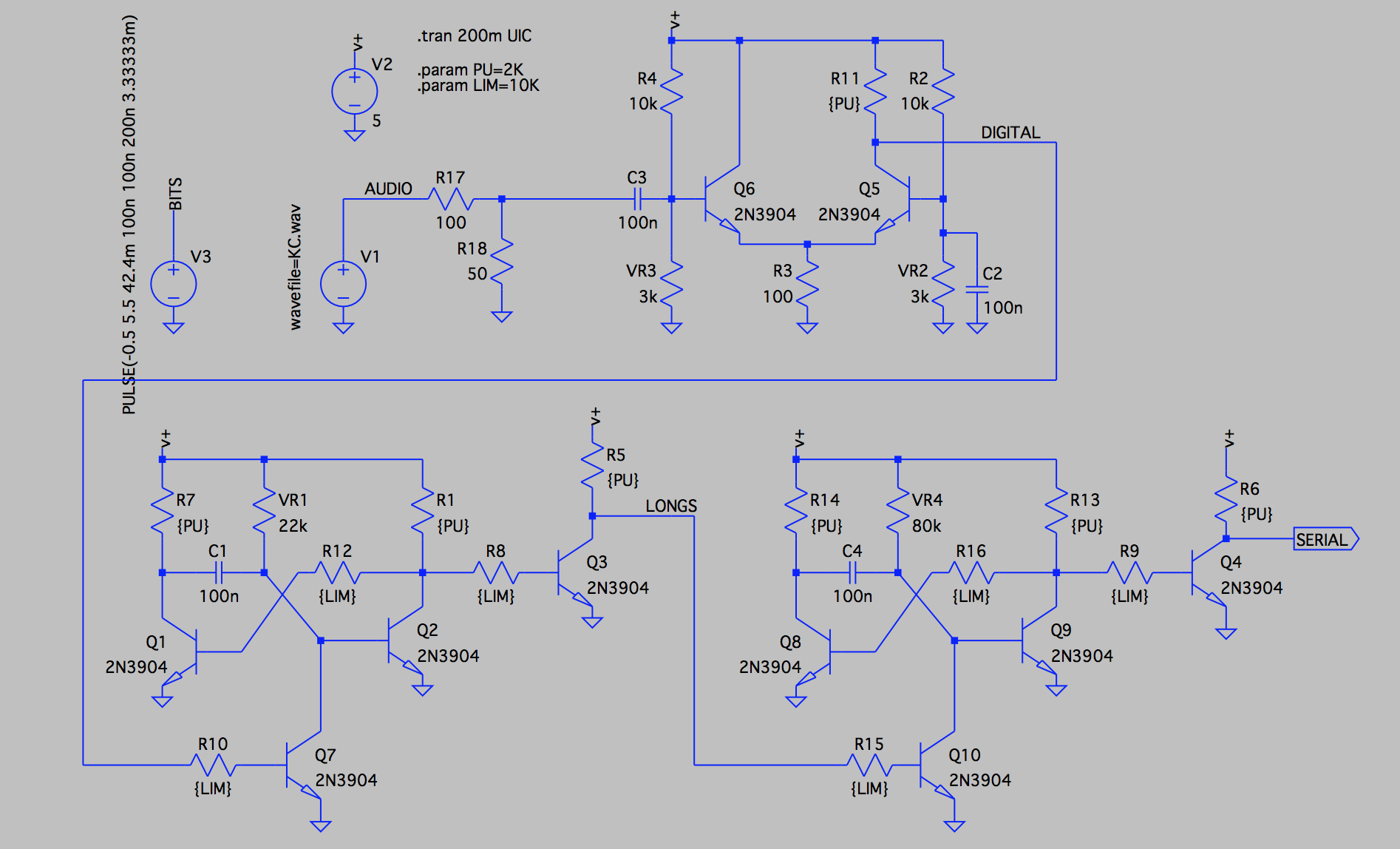
The V1 voltage source is "playing" a wav file with the data from my simulated KC tape. Since the output level is a bit too high I start of with a voltage divider bringing the level down to 250-300mV.
For the amplifier/shaper/digitizer I'm simply using a long tailed differential amplifier-like contraption. It works kinda well, and I suppose it might be done in a better way but I'm not too picky here as long as the number of components are not going through the roof.
We now have a decent digital waveform with a 0-5 volt swing.
This is fed into a monostable flipflop that is reset whenever the incoming waveform is at high level. When the incoming waveform is going back to low the flipflop will timeout after about 300 us. Since a 2400 Hz tone is 208us low/208 us high, and a 1200 Hz tone is 416us low/416 high this monostable will never have a chance to timeout during a 2400 Hz tone, but will do it during the periods of 1200 Hz.
So at this stage we have a steady level during a 2400 Hz tone, and a train of short pulses during the slower 1200Hz.
Now we need to detect this pulse train and make it into one continuos level. This is done with yet another monostable flipflop. The pulses have a low period of 810us so the second monostable have a timeout of about 1100us.
So as long as we have this pulse train the monostable will be retriggered and be active all the time, and when the pulse train stops it will timeout.
The output of this a UART-like serial bitstream that is idling at a high level, and have a low level start bit.
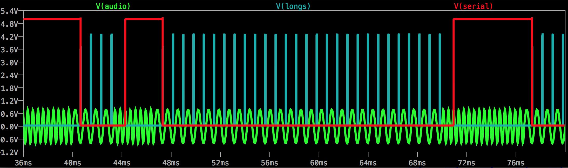 The green trace is the incoming FSK audio staring with the idle level 2400Hz. At 40ms it switches over to 1200Hz for the startbit. The cyan traces is the timeout pulses from the first monoflop that is set to timeout whenever its input is low for more than 300us - which it is during the 1200Hz tone. These pulses are triggering the second monoflop to generate a low level (red) serial output. A soon as the input frequency goes back to 2400 Hz these pulses stop and the serial output goes low.
So this screenshot shows a part of the initial idle state, followed by a low startbit, eight data bits where the LSB is high/1 followed by seven lows/0's, and then finally two high stopbits.
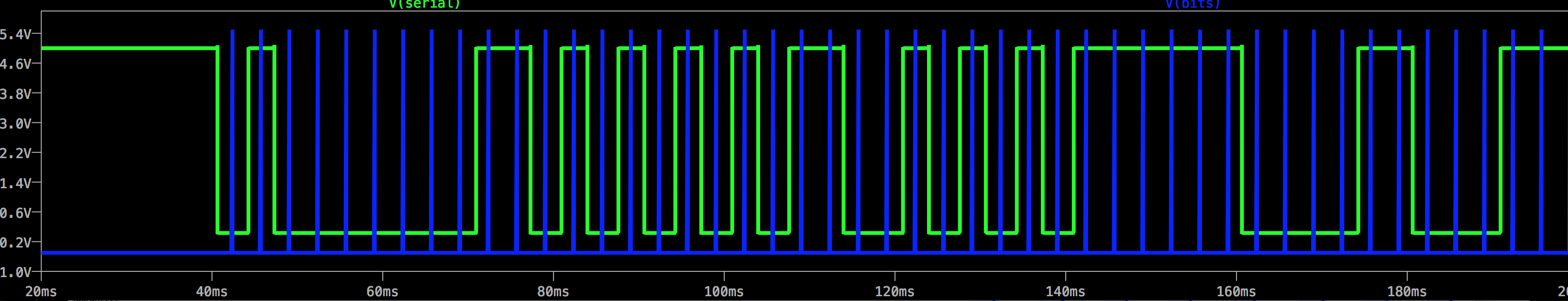
The screenshot above shows the full serial output as taken from the KC.wav file . The serial data is green and a (debugging) signal in blue that shows the sample positions for the data bits. The data is 0x01 , 0x55, 0xAA then a short delay while keeping the idle level and finally a 0x18
Discussions
Become a Hackaday.io Member
Create an account to leave a comment. Already have an account? Log In.
This is really cool.
Are you sure? yes | no