 Jakob
JakobFirst I stared to make a prototype while waiting for the Numitron tubes.
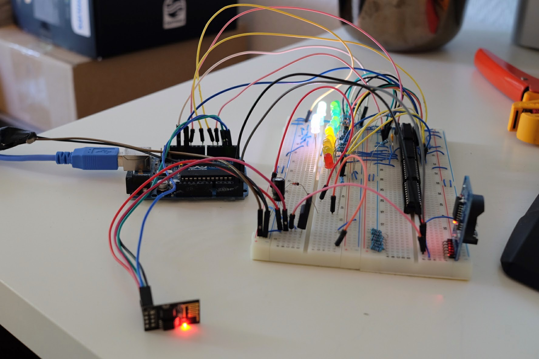
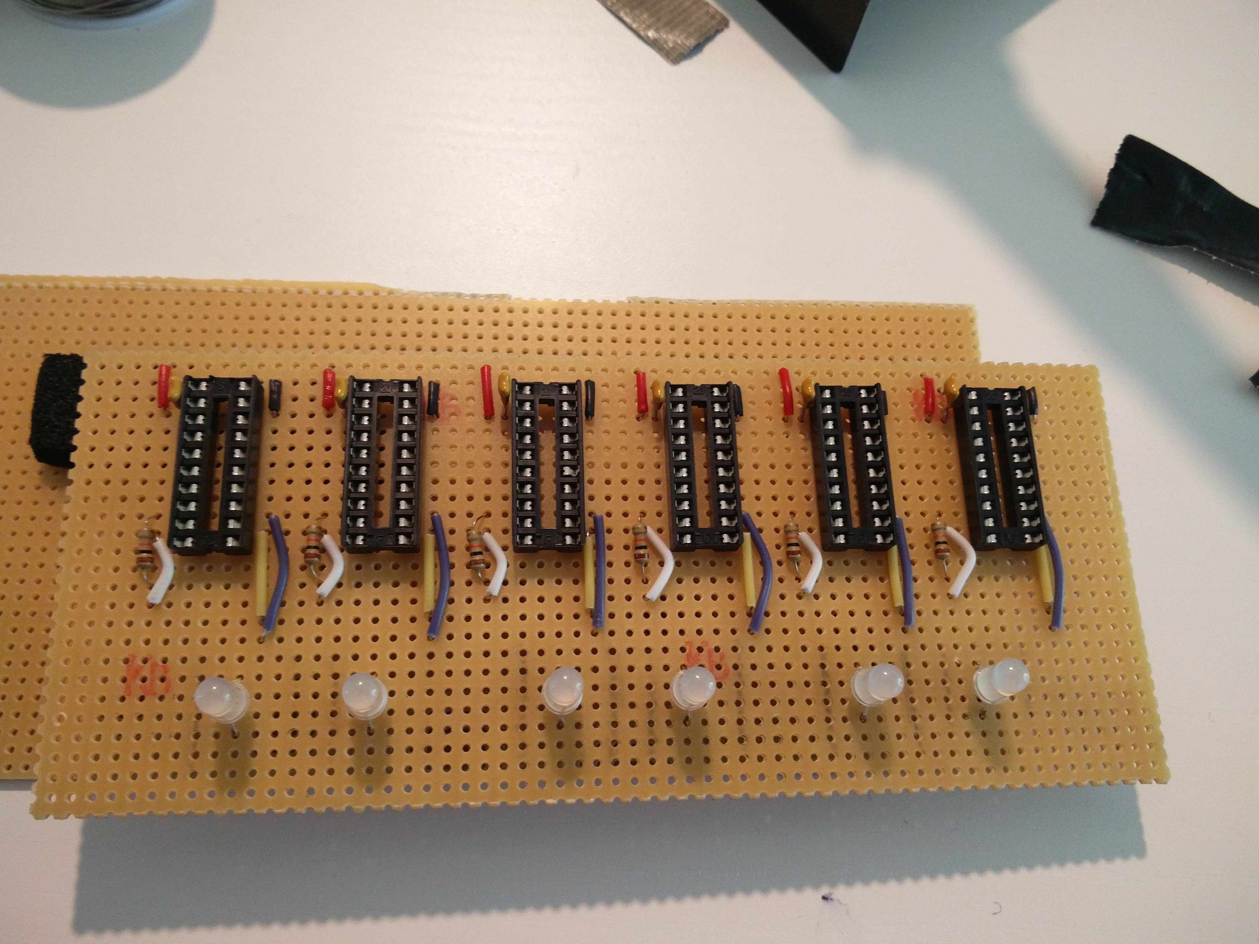
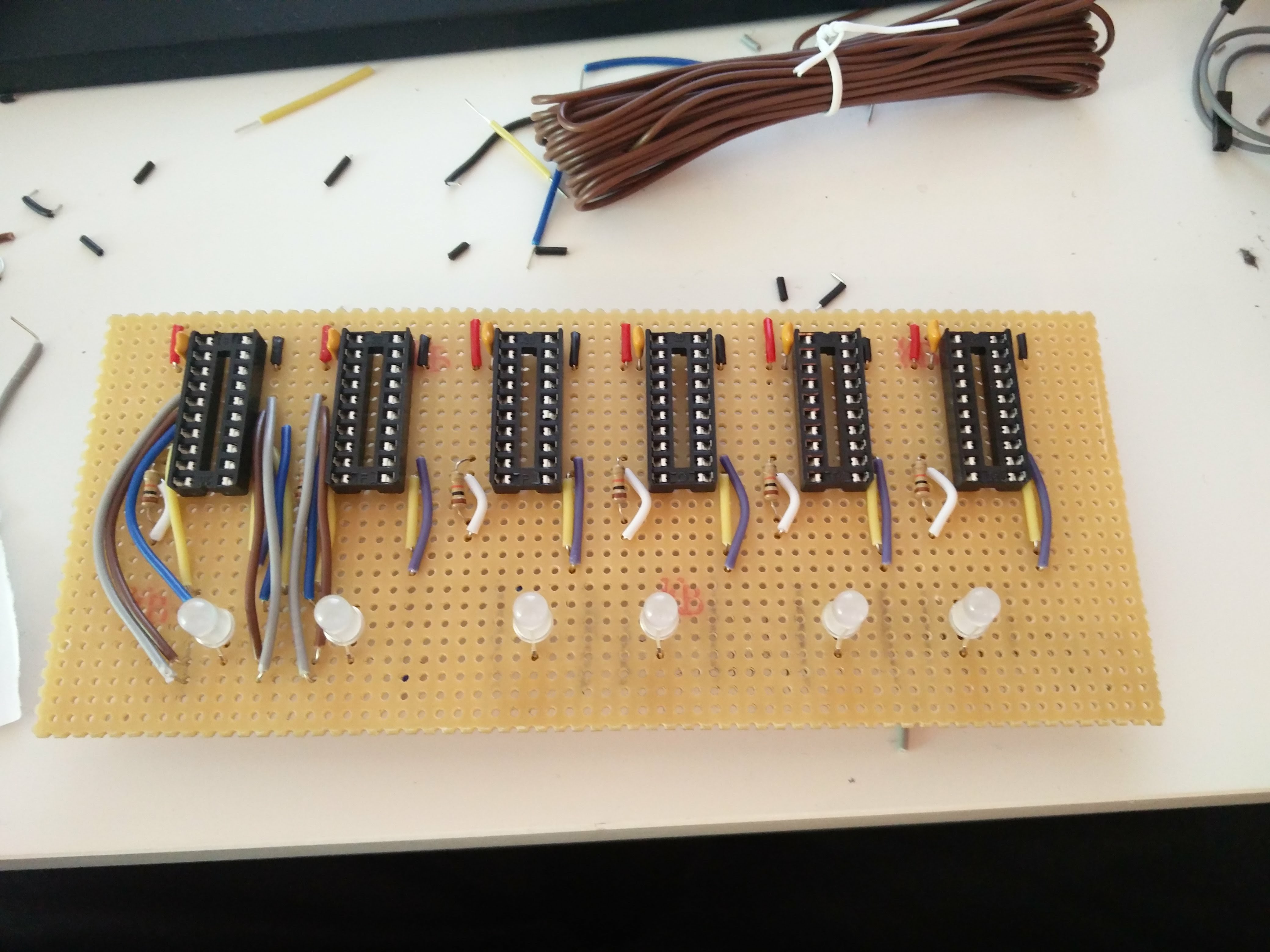
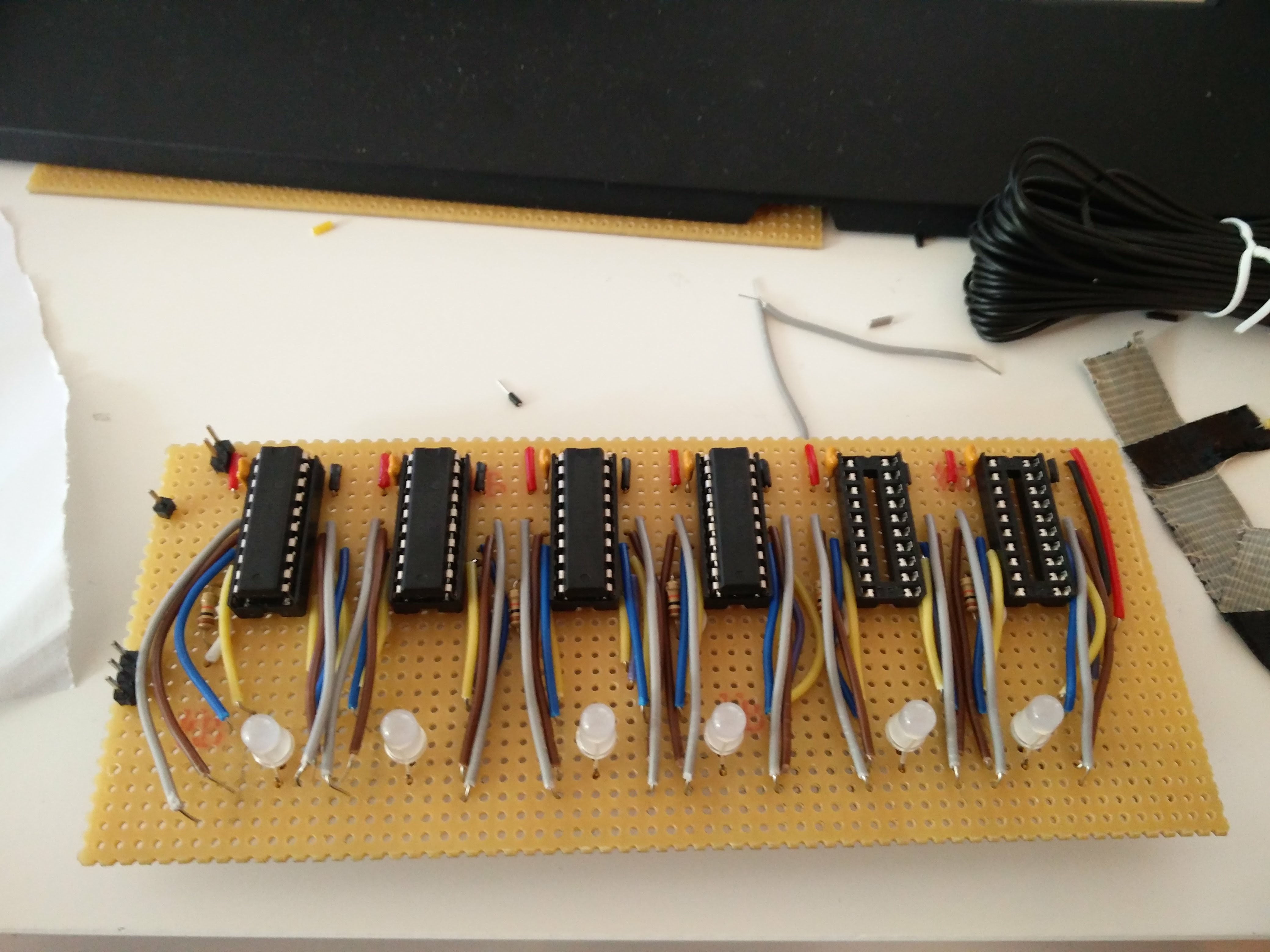
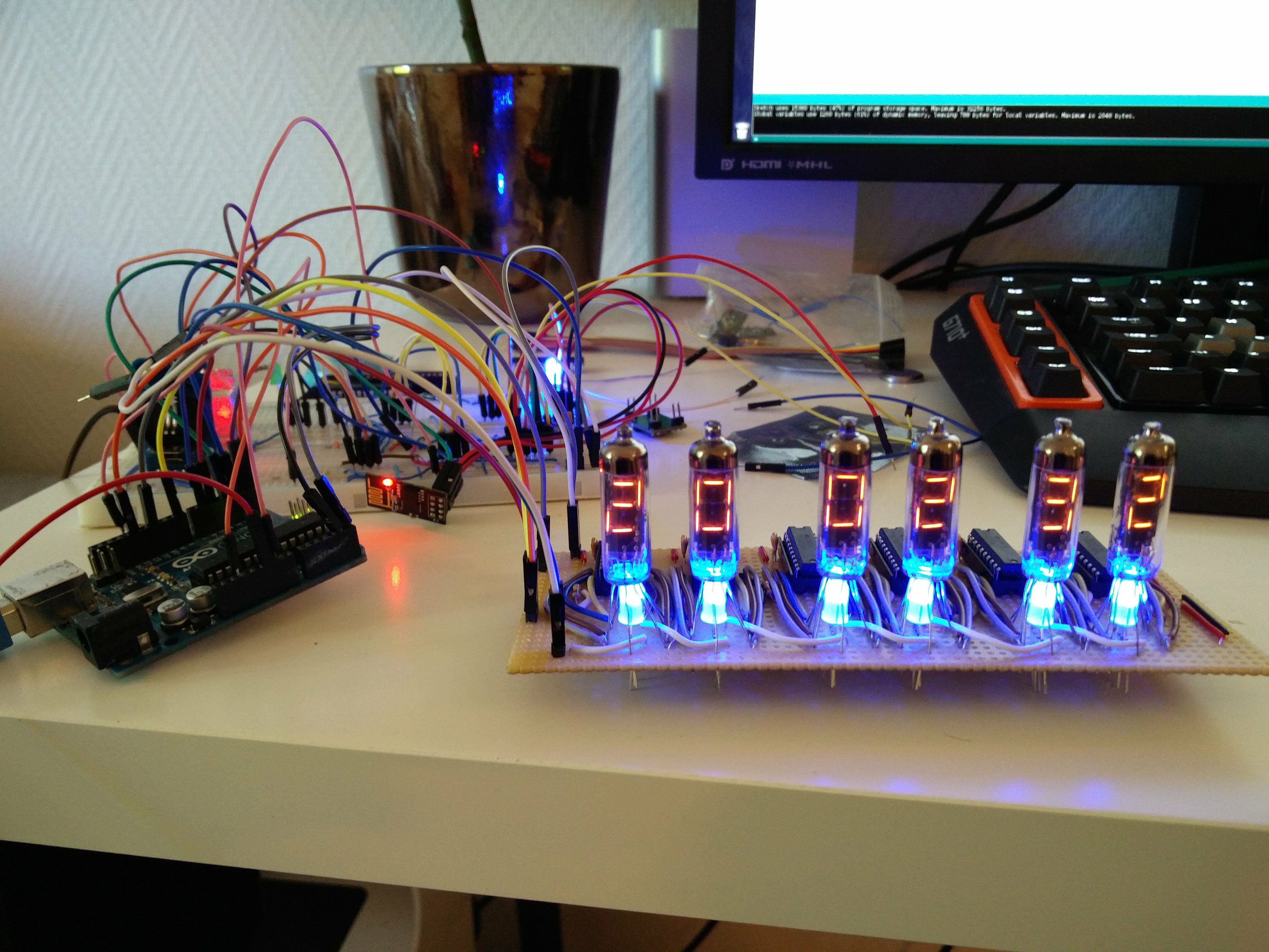
I got everything to work with the shift registers (TPIC6B595), validating using some simple LEDS. Also got the RTC and ESP8266 working properly. Most code was done before I received the lamps.
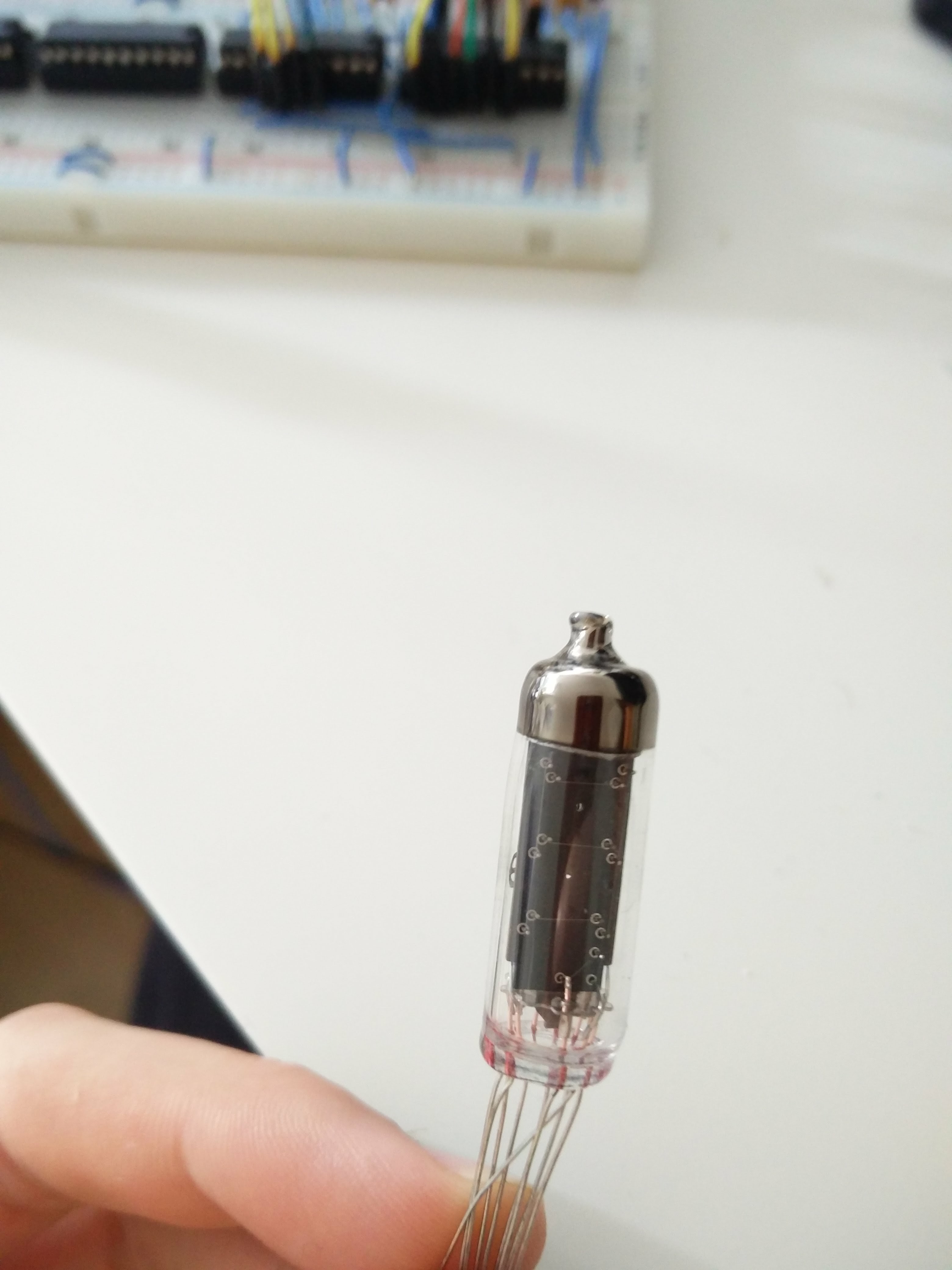
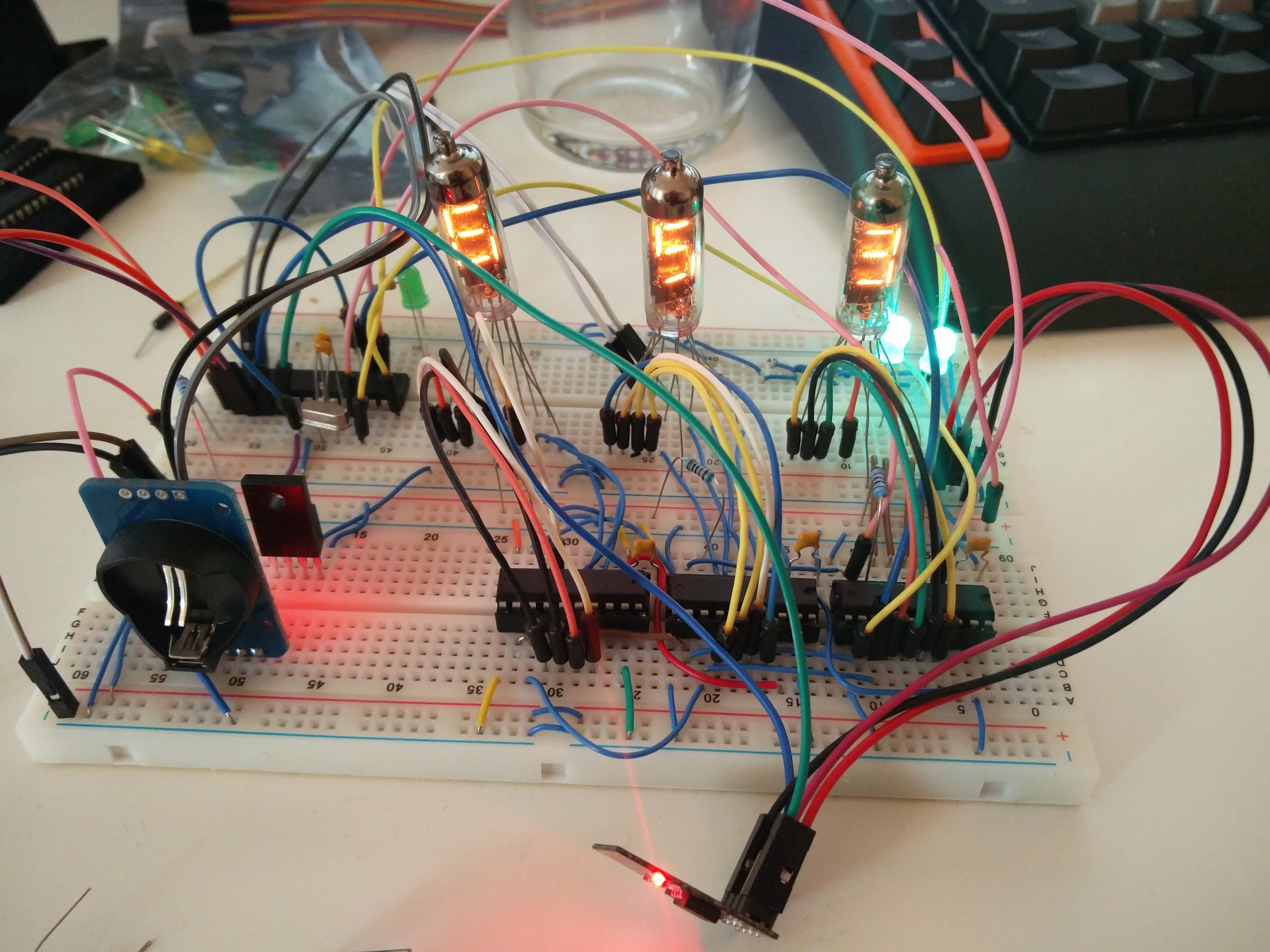
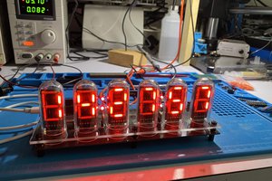
I then received the Numitrons (IV-9), threw them into my prototype, and hey they worked straight away!
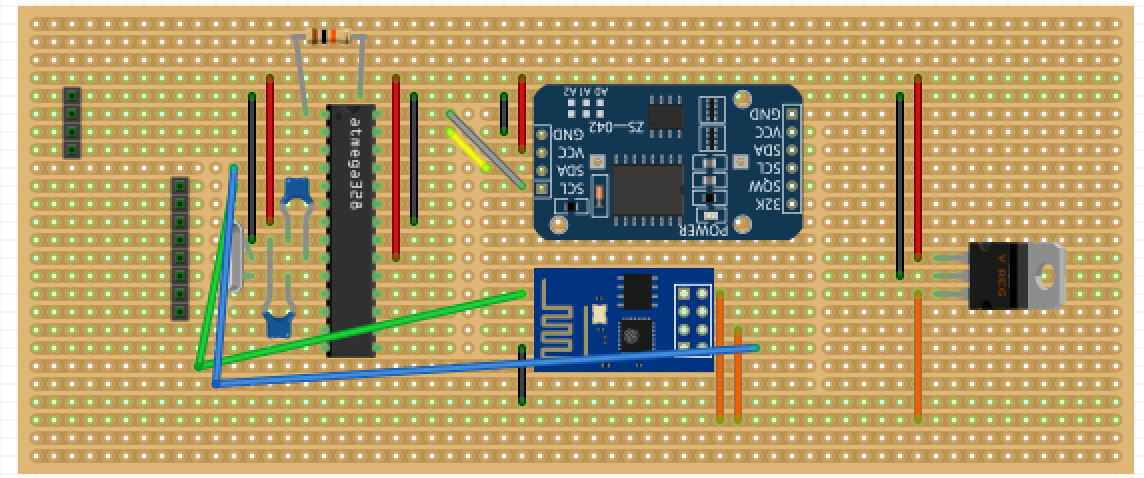
Started with a design using Fritzing. It's a little messy and not very beautiful, but it did the job :)
Some components doesn't have the correct names in the sketch, like 3.3 voltage regualator in the 2nd layer. Also the wires from each shift register to the Numitrons aren't drawn except for the first one.
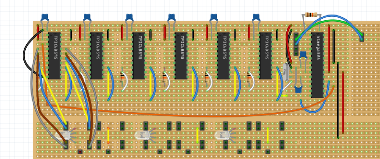
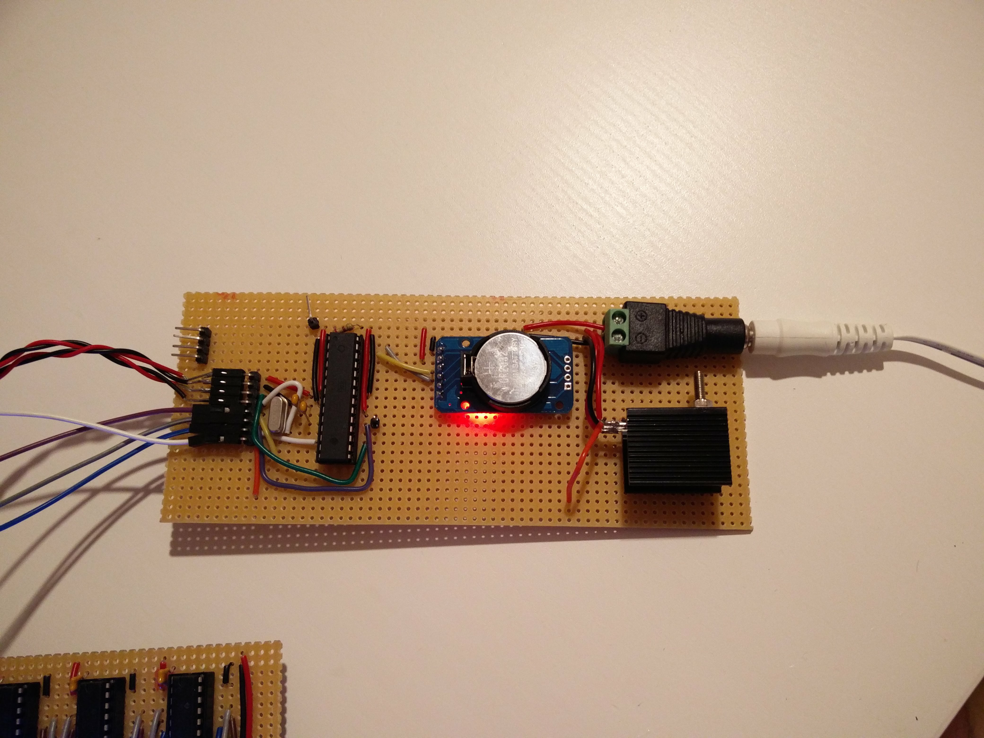
The final board didn't end up looking exactly like this. I later decided that it would look better if I could make it smaller, therefore I moved the atmega 328p down to the 2nd layer. Replaced half of the ws2812b LEDs with yellow wire, so that I could still see. The pin headers at the bottom represents each leg of the Numitrons. Also since Fritzing was insane laggy for me I couldn't be bothered to draw all cuts in the stripboard.
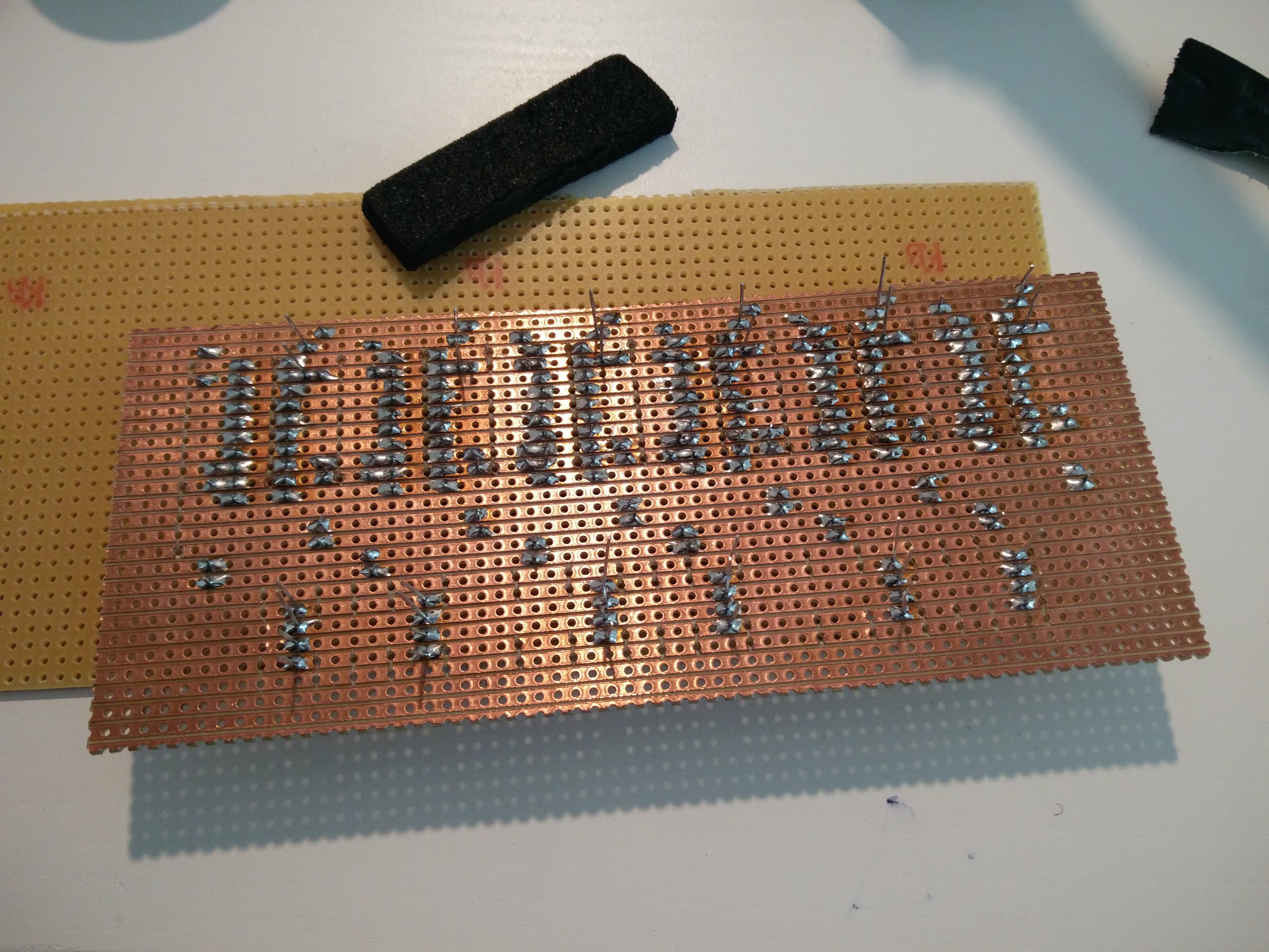
And the layer two:
When this was done I started making all cuts in the stripboard and then finally soldering :)
This is like half way through, lot's of soldering left to do.
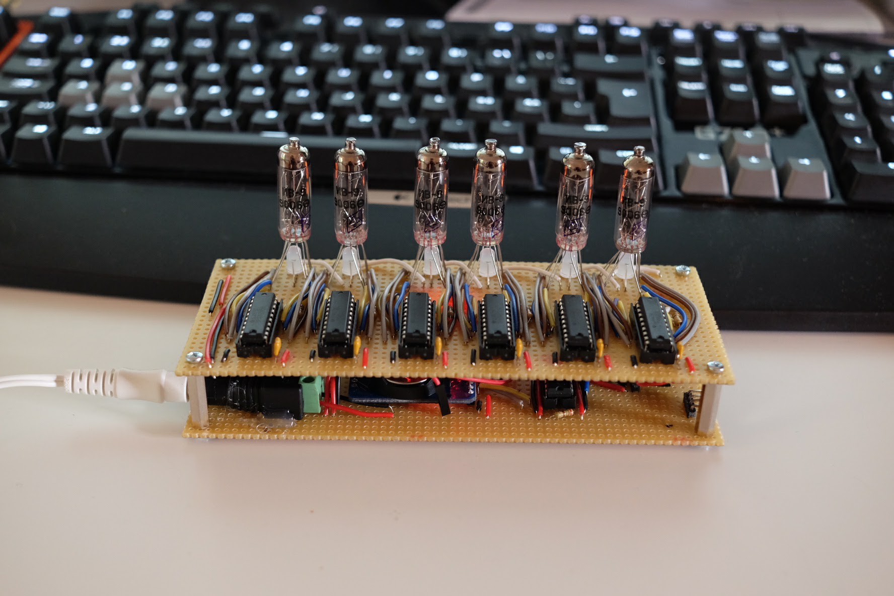
Here all Numitrons are soldered and the new board hooked up to the prototype.

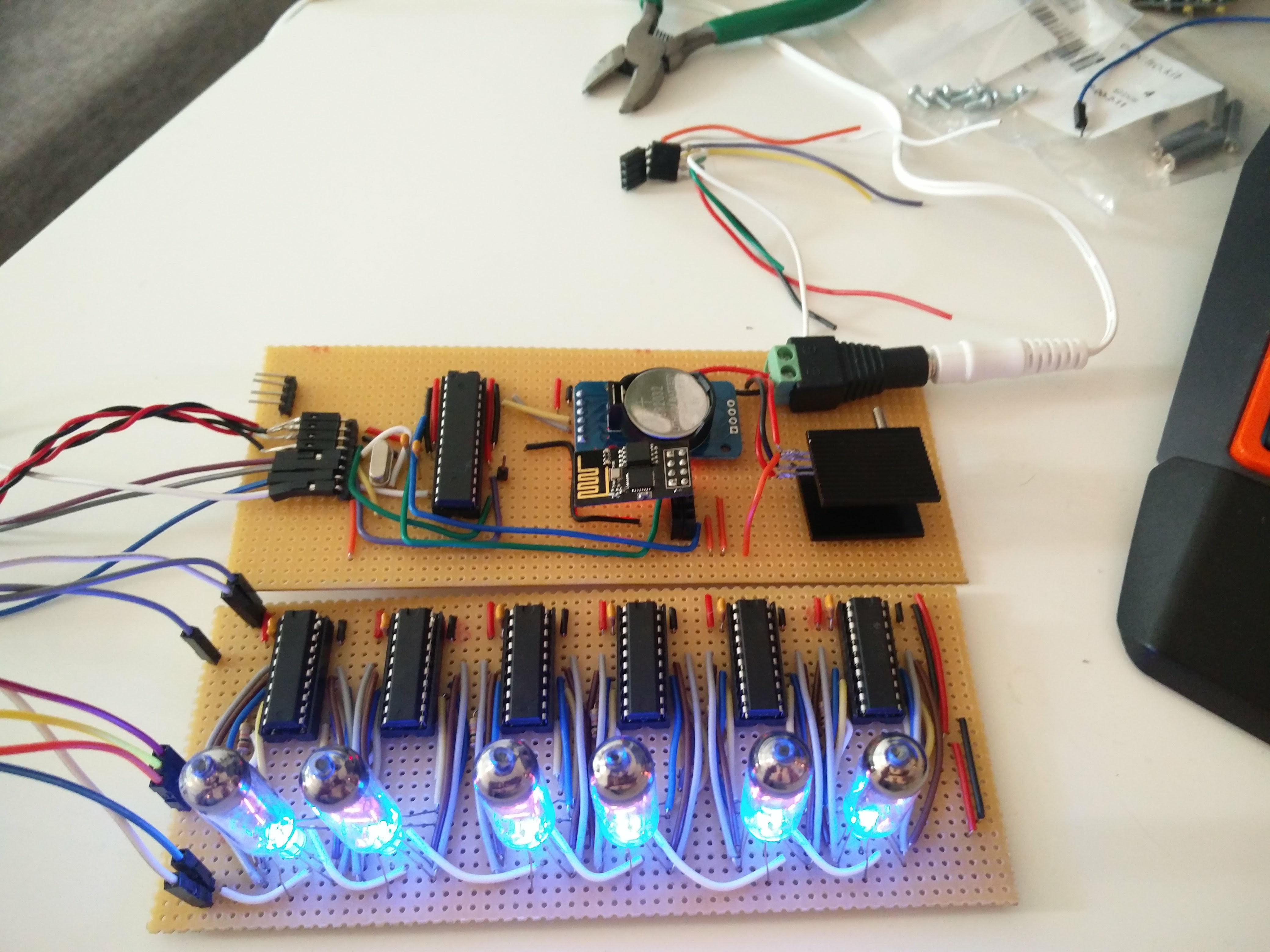
Now I drilled holes in the corners and screwed the two boards together.
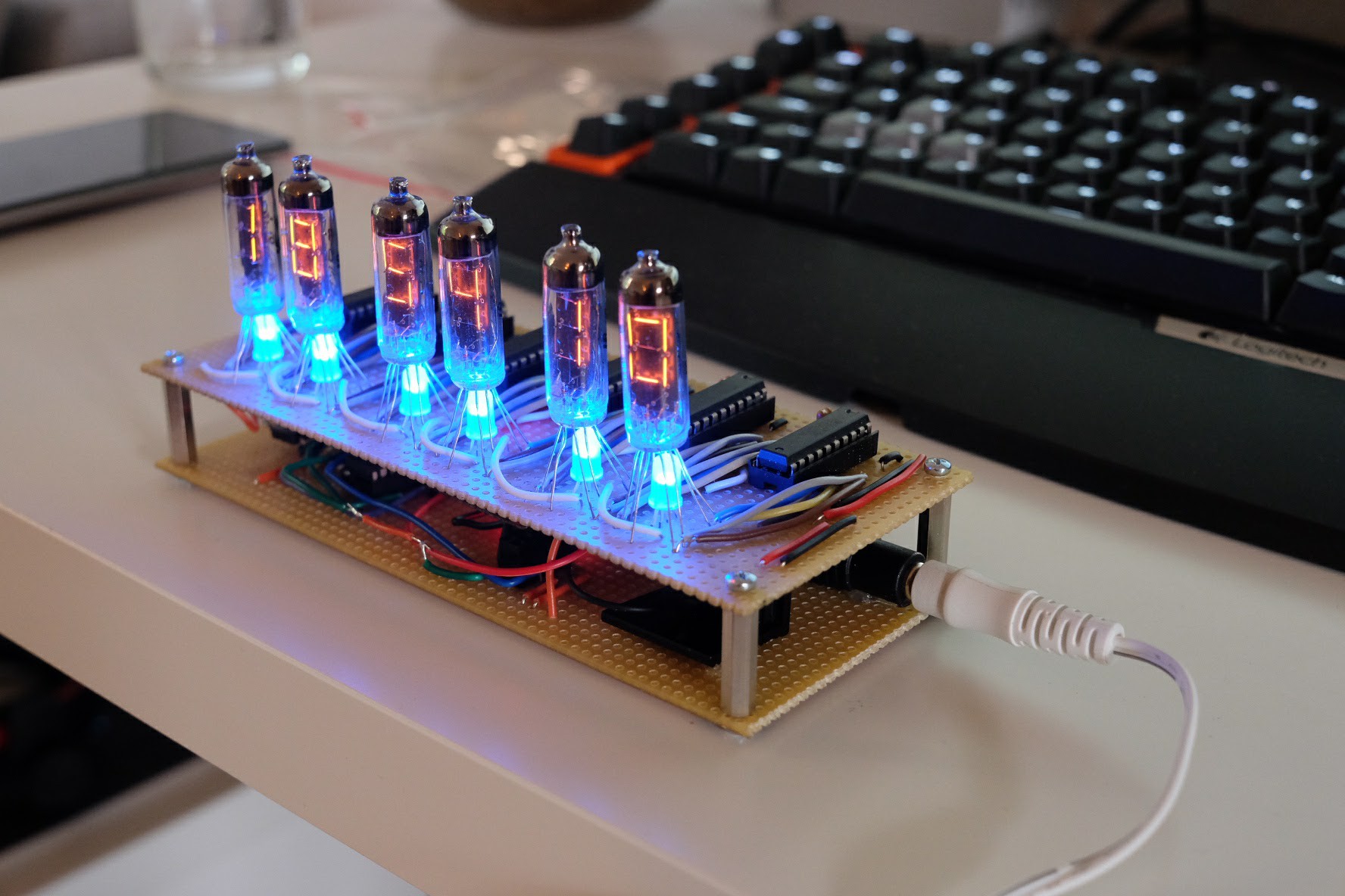
And it's finished! I'm planning to make a case for it in the future :D
 Jay Hamlin
 RRichmond
Any plans to share the code? (edit: NM, I see you shared it on github. Thanks!)