 WJCarpenter
Today, I found another blunder of mine. This one is a whopper in the part of the circuit around the MOSFETs.
I had originally tested the MOSFETs I'm using on a breadboard. They worked as expected with PWM output from an ESP8266. That was a long time ago, and I've switched to using an ESP32. I've also tested the PWM pins I'm using with a simple LED circuit. Again, it works as expected. When I finally got around to testing the MOSFET outputs on the assembled board, I got only a very weak and erratic output.
It turns out that I had not tied the MOSFET source to ground. (These are N-type MOSFETs, to the terminology is counter-intuitive for me; source is ground, and drain is positive [or at least "the other one"].) It's not that I tied it to the wrong thing ... it's that I hadn't tied it to anything except the load. I guess I must have been thinking that it was fine for the load to fill up with electrons forever. Actually, I don't know what I was thinking, but I hope any EEs can get a chuckle out of it.
This was fairly easy to solve since I just needed to jump the source pin to ground. It's not a mere signal, though. It's got to carry to current for the load. So, I tied each source pin to a ground pin from an input power supply. Unfortunately, those are completely across the board from the MOSFETs. Notice the professional looking black wires in this photo:

The bad news is that the board now bootloops. I confirmed it's the jumpers causing it by cutting them. I'm not sure what is causing the problem. My current suspicion is that the MOSFET gate is drawing too much current for the GPIO of the ESP32. (12mA might be a safe max per GPIO https://esp32.com/viewtopic.php?f=2&t=2027) If that does turn out to be the case, I can add a current-limiting resistor. I should be able to do that with the current PCB by brutalizing the gate leg of the MOSFET. Because it's surgery, I won't do that until I'm more confident that that's what the problem is.
...the next day...
OK, I think I have this figured out. It's a couple of related blunders with the same root cause, which is incorrect wiring for the MOSFET. It's crazy, but I just couldn't see the problem clearly in the entire schematic. When I drew the MOSFET part of the circuit in isolation, it became much clearer.
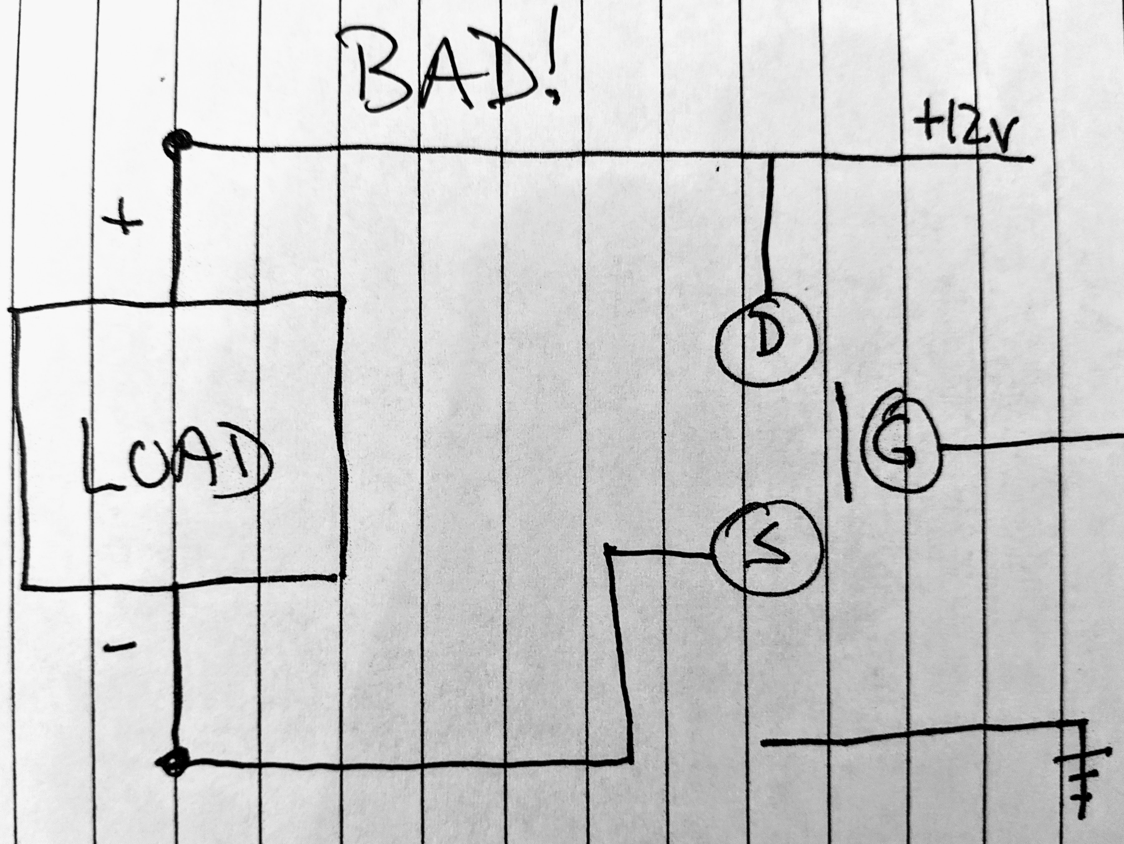
In isolation, here is the circuit as originally designed. It's bad because the electrons check in, but they don't check out.
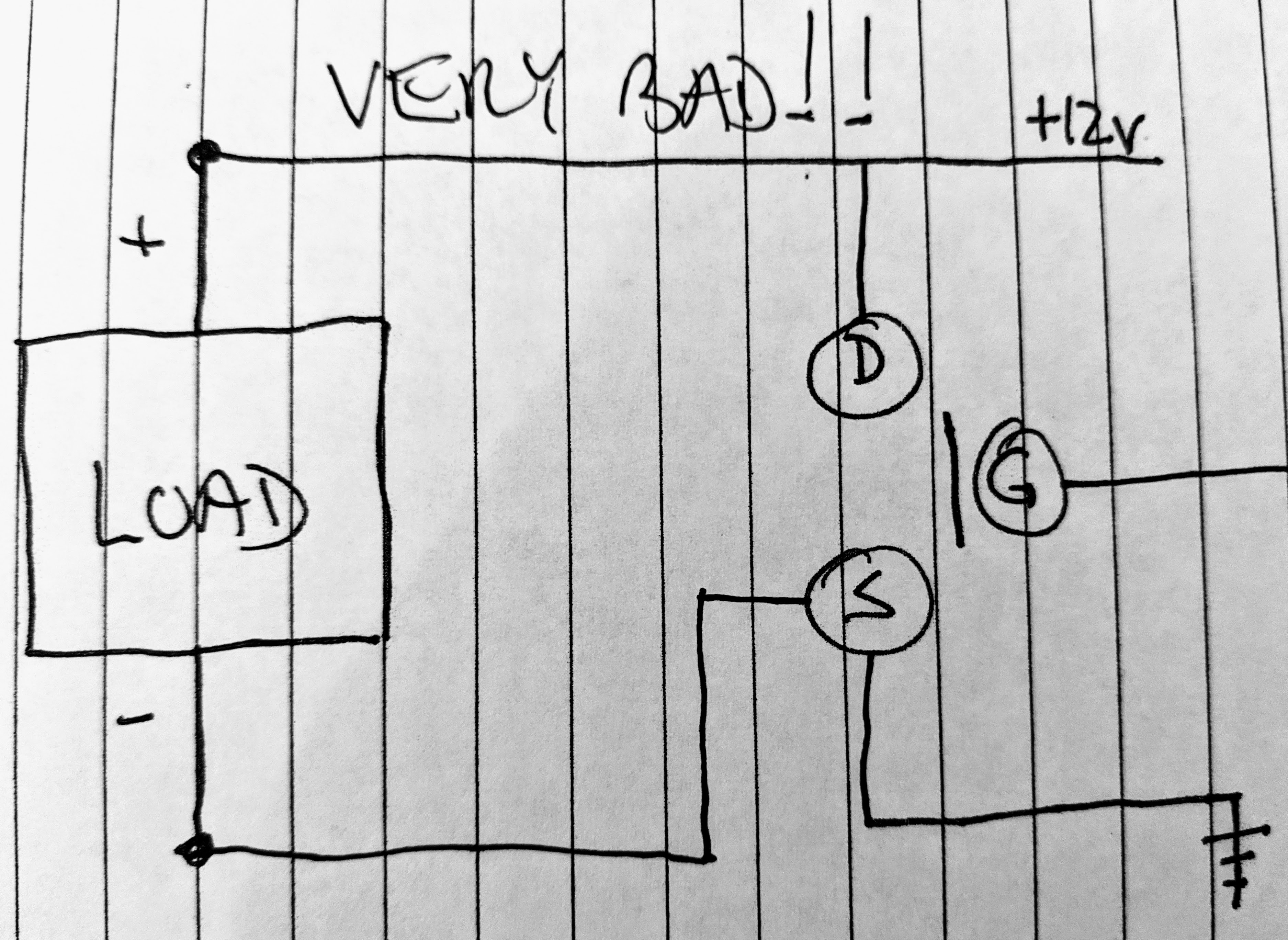
My first attempted fix (described above) was foolhardy and actually made things worse. In addition to providing a way for the load to connect to ground, I actually provided a way for the +12v supply to connect to ground when the gate turns the MOSFET on. It was like fixing a traffic jam by driving all of the cars off a bridge. When the MOSFET is off, the load would be on (the opposite of what I want). Since my current firmware had the gate on at 50% duty cycle, I was shorting the power supply to ground half the time. And that is undoubtedly why I got a boot loop. There was no power left to feed the rest of the circuit on the PCB. D'oh!
Here's a picture of the cure-worse-than-the-disease:
Finally, here is what I think the circuit actually should be. Turning the gate on provides a path to ground for the load. With the gate off, there is no path to ground (for anybody!).
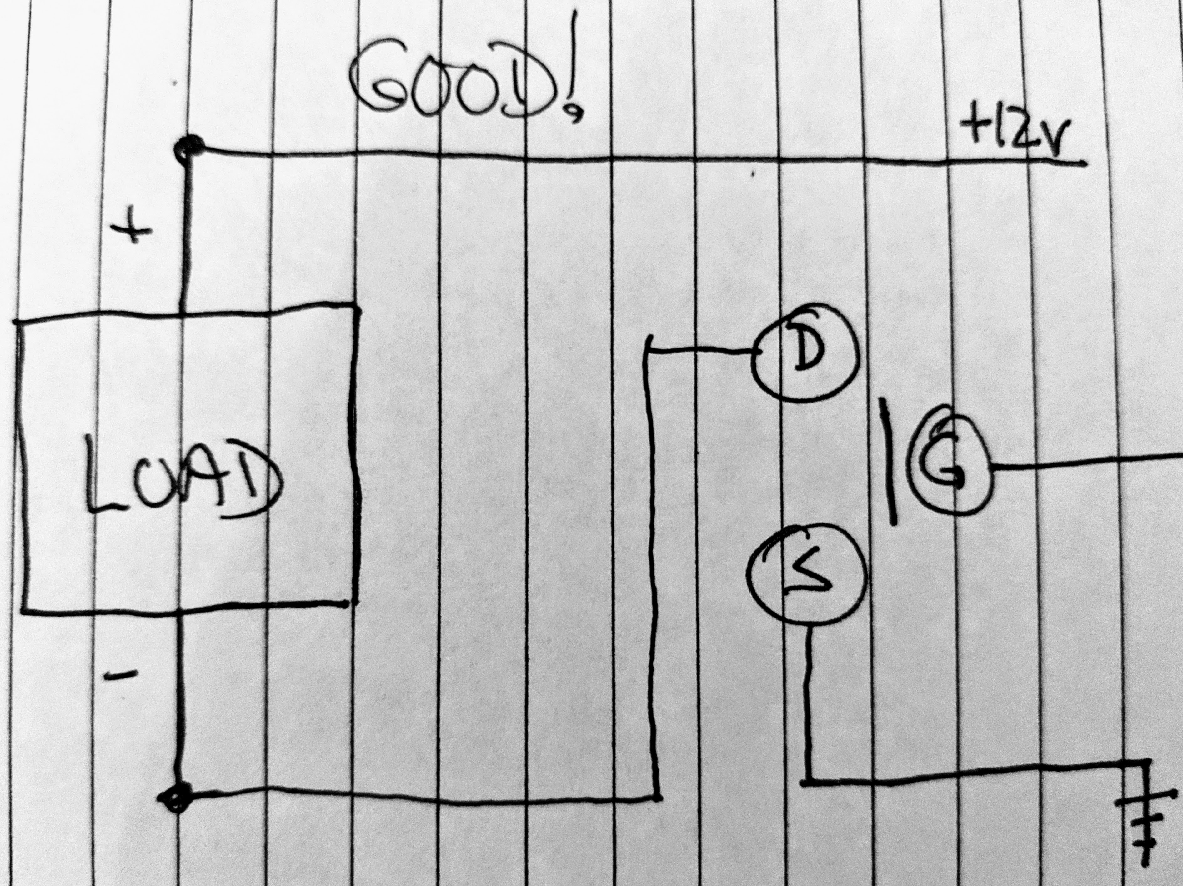
I haven't actually wired things up this "good!" way yet. But it looks right, and I've never been wrong before.
Rewiring means moving the drain leg (pin 2) of the MOSFET to connect to the land currently occupied by the source leg (pin 3). Moving the drain leg will also break the connection from drain to +12v (but it will still go to the load through the now-empty land). The source leg will have to dangle in the air and be jumpered to ground. I'm still trying to decide whether I need to bother with the current-limiting resistor for the gate leg (pin 1). I'll probably will, but I'll make a game-time decision when I'm back at the soldering iron. Whatever I do, the MOSFET mounting will turn from something tidy to something gross-looking.
Discussions
Become a Hackaday.io Member
Create an account to leave a comment. Already have an account? Log In.