 WJCarpenter
Today is about experimenting with driving the MOSFET that will be the dimmer control for the strips.
First, I tried driving it directly with PWM from a GPIO pin. I verified that the PWM does step the gate voltage up and down from ~0v to ~3.3v. I also verified that simple GPIO high/low gives the same result. Nothing unexpected there.
The switching voltage for the MOSFET I'm planning to use is 2.5v (STP16NF06L: http://www.st.com/en/power-transistors/stp16nf06l.html, because I have a handful right here). I did some tests driving the MOSFET gate directly from a GPIO pin, both for simple on/off and for PWM. My switched voltage to the MOSFET (ie, the thing I want the MOSFET to control) is ~12v from a wall wart. With GPIO on/off, I got just about ~12v/0v on the nose. With PWM at 100%/0% duty cycle, I also got ~12v/0v. I did a simple software loop that varied the PWM duty cycle up and down in steps, over and over. I'm too lazy to drag my scope over here, so I just measured that with my multimeter., which updates the display about every half second or so. (I have no idea how frequently it samples.) I saw it go as low as 0.06v (correction, I just saw exactly 0.00v), but only as high as a little under 10v. I suspect that high part is due to some kind of rise time thing in my meter. OK, OK, you talked me into it. I grabbed my much-newer-but-much-cheaper meter. It updates a lot more frequently. I now regularly see it hitting ~0v and ~12v. Yay.
My load for this breadboard test is just a simple LED+resister, so the current is probably around 20mA. I wonder how the load of the LED strips will affect this MOSFET. I plan to use 2 MOSFETs with each controlling a single LED strip. Earlier, I measured the A/C draw for a single strip as 40-45w. Since I don't really know what I'm talking about, I'm going to assume the strips draw a maximum of 45w at 12vdc, or a little over 3 amps.
Now we're off to the races with the datasheet for this MOSFET. I've watched or read several discussions of how to use a MOSFET datasheet, but ... you know. This datasheet has a nice graph for the "safe operating area". That sounds good.
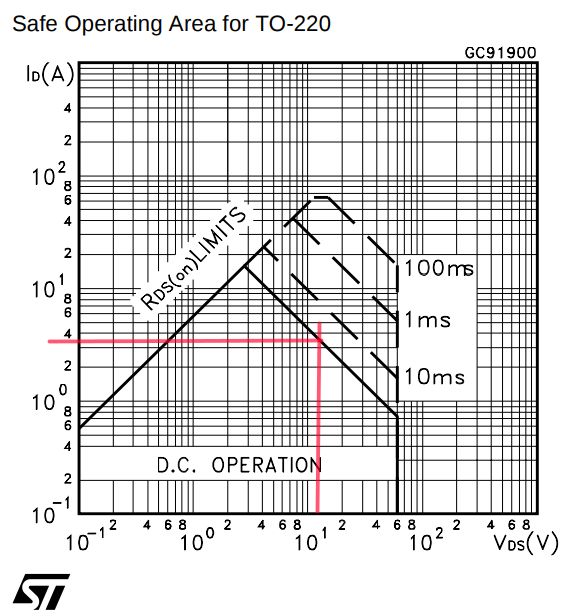
It looks like it can handle a little over 3A of 12v supply, but it's also pretty close to the margin. Let's try something else. ST provides a smart phone app called "ST MOSFET Finder" that will let you do a parametric search to find appropriate ST MOSFETs. When I put in the parameters I've just discussed, the MOSFET I planned to use is not among the search results. Drat. I guess I have no choice but to actually measure the DC load of one of those strips. Wait right here.
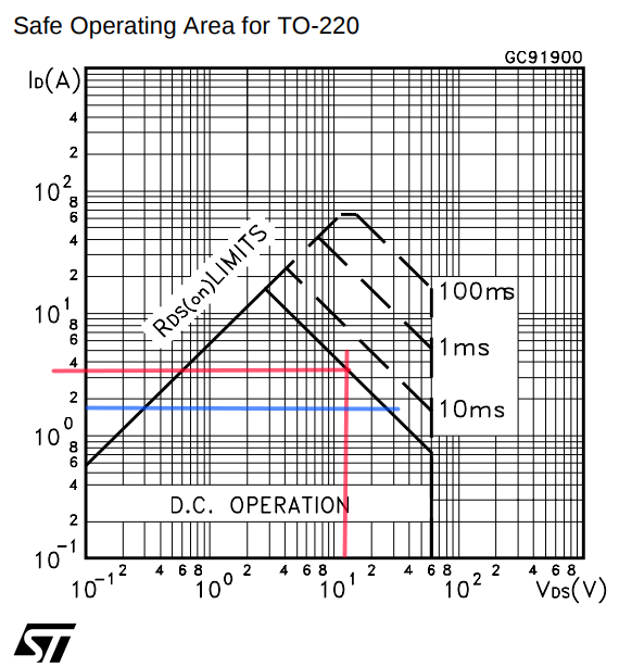
Things are looking better. With the power supplies that came with the strips, they are drawing 1.5A @ 12.6V, or <20W DC. That puts us well within the safe zone.
What about heat? This guy's video provides a pretty clear explanation of how to calculate that from the datasheet. Following his calculations, I get about 1/4 watts of heat and about a 15 C rise in temperature with no heat sink. I doubt that it's ever been as warm as 50 C in my garage. 15 C + 50 C == 65 C is well under the max operating junction temperature of 175 C, so I think I just have to worry about melting something in the case I use to mount these. I'm most likely to use a fairly standard wall-mounted electrical box. The common blue PVC boxes available in the US are typically rated for 90 C conductors. That seems like plenty of margin.
Discussions
Become a Hackaday.io Member
Create an account to leave a comment. Already have an account? Log In.