 WJCarpenter
Remote from the main controller board are 2 rotary encoders with switches and 2 PIR motion sensors. Each remote box also has a separate LED for feedback/indications. With shared ground connections and shared 3v3 connections (where possible), that implies 6 wires for the rotary encoder remote boxes and 4 wires for the PIR remote boxes.
I'm using Cat3 cabling for the runs from the controller board to those remote boxes (including for the PIR remote boxes, where I only need 4 wires*). Cat3 cables is also known as 6P6C (6 pins, 6 conductors) and consists of 3 distinct pairs of wires. I'm using this kind of cable because (a) it's cheap and widely available, and (b) the standardized color coding of the wires is very helpful: blue, blue/white, green, green/white, orange, orange/white. The abbreviations for those colors is on the silkscreen for the PCB and simplifies hooking things up. To facilitate easy removal of the controller board, I used keystone jacks to wire up short lengths of Cat3 to the screw terminals. There will be matching RJ12 plugs on the cable ends nearest the controller board.
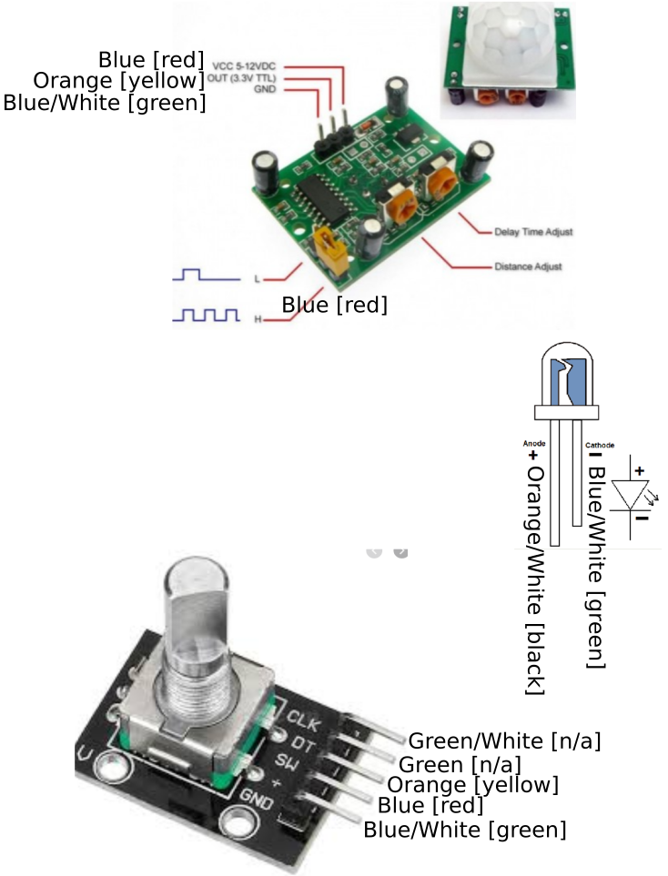
(*OK, a little white lie. When it came time to run the cable, I ran short of Cat3 by several feet. So, one of the PIR remotes uses standard 2-pair telephone wire, which uses a different color scheme: black (orange/white), red (blue), green (blue/white), yellow (orange). Luckily, I arbitrarily [I think] didn't use green or green/white on my PCB markings, so I can be slightly less confused when wiring this up.)
Here is a diagram of the pins of the components in the remote boxes with labels for the wire color coding. The color names in the [square brackets] are for the 2-pair telephone cable as an alternative to the Cat3 colors.
Discussions
Become a Hackaday.io Member
Create an account to leave a comment. Already have an account? Log In.