 Yann Guidon / YGDES
(moved from the project description page)
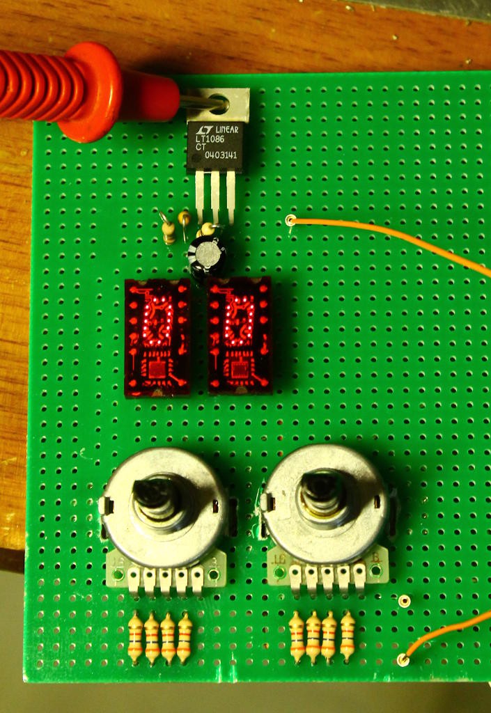
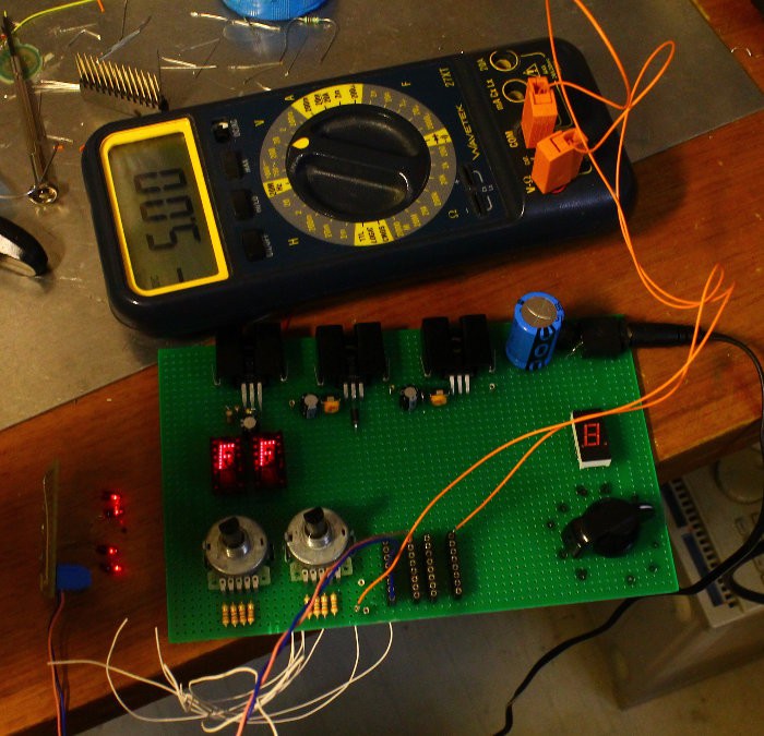
Since I want to program both 74187 and 74188, I need 8 bits of input and 8 bits of output. I started with my favourite parts: a couple of hexadecimal encoding wheels and a couple of TIL311 for the address bus.
The data bus is a bit unusual : one of the data bits is shorted to 0V, so I use a 11-positions rotary switch (leftover from the #Clockwork germanium discrete clock project) to select the desired bit. For the lower nibble (in the 74187 case) I might add a TIL311 for inspection of the output but LEDs should be enough otherwise. A 7-segments module is used as well to check the output.
The fuse is blown when the power supply is raised from 5V to 10.5V. The different voltage sources are isolated by diodes so approximately 5.6V and 11.2V are required. Add to this that the TIL311 are undervolted at 3.6V... That's a few diode drops, but too close to the margins to use LM317s.
Starting from 12V, two diode drops provide about 10.6V but this is not accurately regulated and might affect the programming. A 14 or 15V input source would allow the use of a LM317 so the power supply would be a 12V unregulated "wall wart" (let's see what I have in stock).
From 10.6V down to 5.6V, another LM317 drops 5V. This is probably the one that dissipates the most power.
Then from 5.6V to 3.6V, two volts are dropped but the TIL311 power rail does not need a tight regulation so a string of 3 silicon diodes would do.
The TIL311's current is measured in the 125mA ballpark (around 60mA per module) and this is the most consuming circuit. The power drops are: 1/4W for the 2V drop and 0.7W for the 5V drop. This is significant but still in the range of the circuits made in the 80s... The good side is : this current keeps the LM317 in the regulation range. In the end, the wall wart must provide at least 200mA (probably rated at 500mA) and most of it will be turned into heat.
I found several LT1086, in fixed and adjustable versions, with are low dropout versions.
Minimum load current less than 5mA, input voltage is high enough (25V max) and the dropout does not exceed 1.5V at max current. That's just enough margin for the input regulator (11V) and the TIL311 rail (5.6V to 3.6V) without weird hacks.
Let's start with the 3.6V rail : I got the regulator and I just have to add a couple of resistors to set the voltage. I find that the ratio of resistors is 2.88 so if I set one resistor to 1K Ohms, all I have to do is find a 2.88K-1K=1.9K resistor. Fortunately this is close to the standard 1.8K value, and the voltage does not need high precision. There is also a need of capacitors but that's not a critical consideration... 100uF/25V will do, I have a significant number of them in stock. Ahem.
The 1.8K and 1K resistors give about 3.59V which is pretty good :-)
This works quite well when you don't mistake a fixed with an adjustable version. And it also made me devise a little trick to calculate the resistors : just convert the volts in kiloohms :-) With a 1.2K resistor for the adjust pin, if I want 3.6V I need 3600-1200=2400 ohms. This is less reliable because of the disturbance of the adjust pin's current but we'll add a trimpot later.
For the 5.6V part I'll use a different trick that the datasheet suggests:
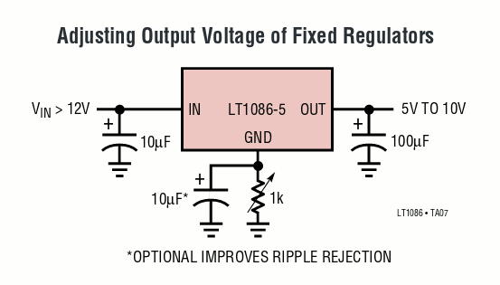
If we consider that 1K provides a 5V swing, 1K/5=200 ohms will provide the required 1V swing :-) That's possible though if I haven't burned the first LT1086-5 that I mistook for an adjustable version for my first attempt...
(Now I realise I could have used this trick because I have 3.3V versions and that would have saved one resistor)
With a 330 Ohms trimpot, I can vary the output from 5V to 6.8V :-) This amounts to about 180 ohms per Volt so a 1K resistor will increase the output by about 5.4V, resulting in 10.4V.
Using a 990 Ohms and the same type of 330 Ohm trimpot, I get a range of 9.6V to 11.2V, which is perfect. The 10.5V output is obtained with the trimmer at approximately half position.
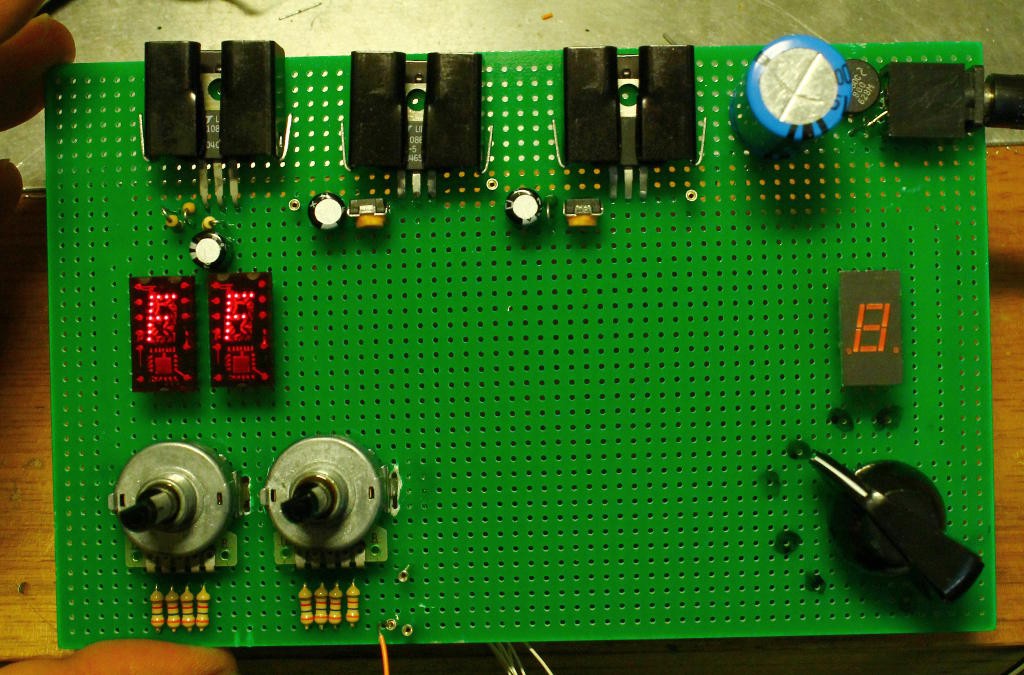
For the PSU, I have a 12V 500mA AC block so a diode bridge and 2200µF 25V capacitor will do. Current draw with just the TIL311 as loads is about 120mA and the filtered input of the whole string of regulators is 14.75V. I've put dissipators on all the LT1086s because the whole thing is just sitting there, dissipating power... But hey, they are regulating well ;-)
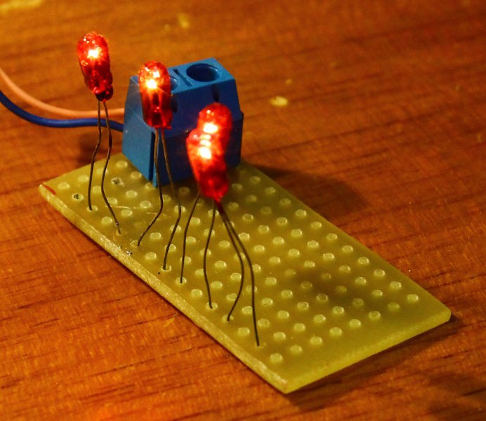
The stage is set now, the actors (power rails) are working, now we have to make them... do something. At this point, the next circuit to design is the one that allows the PROM's Vcc to increase from 5V to 10.5V. Other circuits (see 1. References) use a diode on the Vcc rail and the 10V is pulsed either with a transistor, a relay or a push-button. To complete this circuit and ensure it works as intended, the PROM chip must close the loop (to ensure that the current is right) but it's too early yet. I don't want to burn or damage chips and I'll need a dummy load... What can resist at 10 and 5V ? A resistor but this is going to heat (even more). So I'm looking at something that heats but not too much, such as... an incandescent bulb ?
Fortunately I had already hacked a few Glühbirnchen as a 12V load. I measured the current draw : 30mA@5V and 45mA@11V, this is pretty compatible with a bipolar part :-)
The 5V diode is a basic 1N4007. No need of a larger one, but not sure a smaller package would be reliable.
Once the 5V rail is loaded through the diode, I can adjust the 5V regulator to precisely 5V. With this added load, the input voltage at the first regulator is 14.3V.
Then, how do I switch the 11V rail ? Electromechanical methods are not appropriate because I want a totally electronic control, in case I control it with a Pi later. Transistors then, P-type but Bipolar or MOSFET ?
- Bipolar might be simpler but the dropout voltage is not precise (I'd like a 100mV precision)
- MOSFET can have low losses but are not "vintage"...
I have to choose between the SI2301 and the 2N2907, but I'll give vintage (1973, 0.6A, 60V, 400mW) a chance :-)
So how do I push the 2907 hard into saturation ? With quite a lot of base current, of course. But how much is too much ? This is not indicated but one datasheet mentions Ib=50mA. That's probably almost as much as the programming current... So let's say 20mA (nice, just what a LED needs :-) )
Vce(sat) <= -0.4V at Ic=-150mA and Ib=-15mA
Vce(sat) <= -1.6V at Ic=-500mA and Ib=-50mA
20mA seems to be good enough and a LED in series with Ib will show the programming status. It's the right time to find an old LED from my antiques archives ;-)
The LED drops 1.8V at 20mA, Vbe=0.6V so the LED gets to a minimal voltage 10V-0.6V-1.8=7.6V. The proper base resistor's value is 7.6/0.02=380 Ohms. 390 will do :-) => I get 20.6mA of base current with a nice, not very bright red glow.
The added load and the transistor shifts the Vpp to the range 9.40 - 10.93V with around 70mV of drop through the transistor (not bad, not bad). I'll have to 'scope the transient response...
Discussions
Become a Hackaday.io Member
Create an account to leave a comment. Already have an account? Log In.