 agp.cooper
Guest Post
This is a guest post for Yann.
Firing up an old PROM Programmer
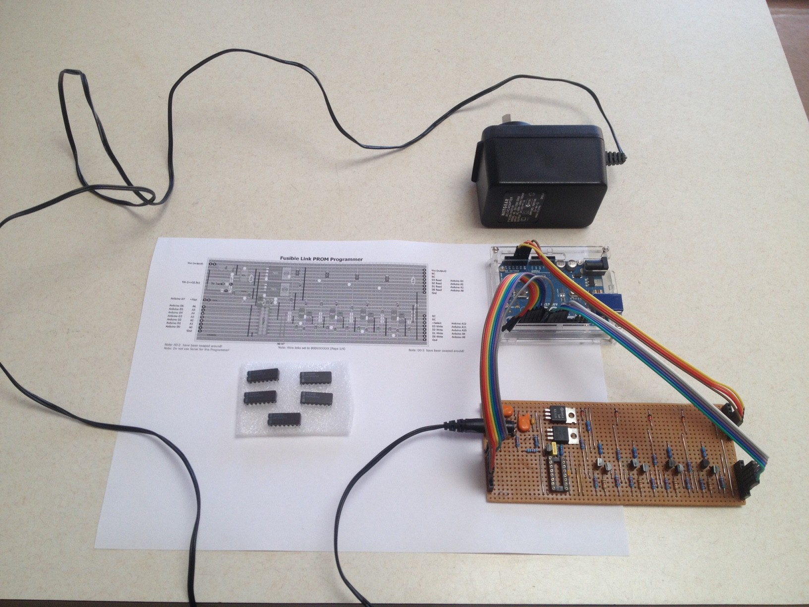
I built a PROM Programmer for my Weird CPU a year or two ago:
My PROMs were the 74S571 rather than the 74188 that Yann is consisdering, but really that is not material for this post.
Programming Guides
I have looked at the programming guides for the various PROMs, although the programming guides are sometimes quite different (surprising!), I feel safe to say that if the PROM technology is the same and the programming voltage is the same, then the programming guides would be interchangeable.
The programming guides however do suggest problems with the technology which really do need to be managed. The main one is over heating of the chip during programming cycle. The second one is the programming voltage rise time.
The main conclusion is that you should drive your PROM Programmer with an Arduino or similar if you want to follow a programming guide. Even if you don't follow the programming guide exactly you are still better off with an Arduino managing the programming cycle.
For Ti-W technology (Yann's and my device) the voltage (10.5v) pulse rise time needs to be between 1 us to 10 us (i.e. between 10V/us and 1V/us).
The nominal programming duty cycle for both devices is 25% (i.e. no more than 25%).
Generating the Voltage Pulse
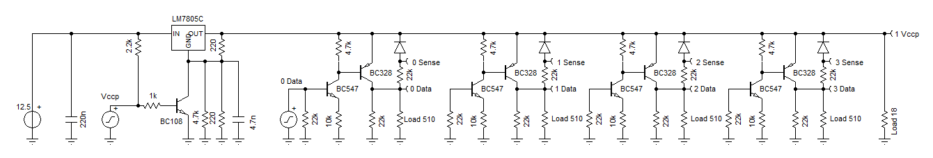
The easiest way to do this is to use a 12.5v or higher voltage supply (but it must be able to supply 1A) and a voltage regulator. All that needs to be done to the voltage regulator is to adjust the feed voltage to switch the voltage. We can do this with a transistor. In order to control the voltage pulse rise time we just control feedback voltage rise time. Here is my design:
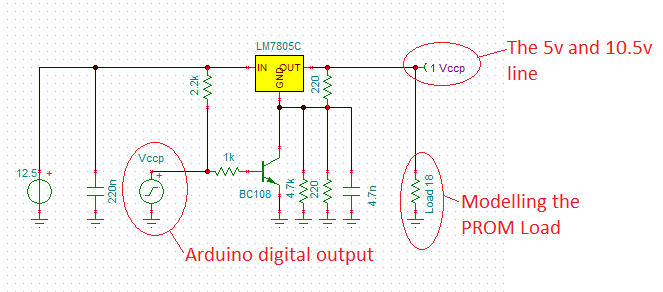
The 2k2 resistor between the power supply input and the Vccp input is designed to ensure the output voltage stays at 5v if the Vccp connection (now call VPP) is broken. The 4.7n capacitor controls the pulse rise time. The 4.7k and the 220R resistors are for fine tuning of the 10.5v voltage output. Here is the voltage pulse signal:
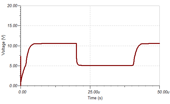
The pulse rise time needs to be in the order of 1 us to 10 us (check it is!).
Programming the Bits
To limit current into the PROM output, the bit programmer (yes the device is programmed one bit at a time) needs to be able to go tri-state when off. Here is my design using common transistors:
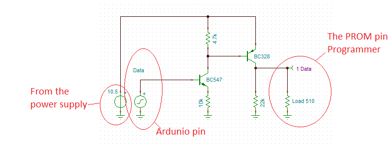
I used transistors because they can handle the current with low voltage loss. The BC328 is perfect for this application. The BC547 just needs to be high gain.
Yann asked about the 10k emittor resistor? It increases the transistor input impedance and limits the transistor current.
Sensing the output of the PROM
The final version is a little slow (~2us) but works well:
I redrew the schematic just to make things clearer:
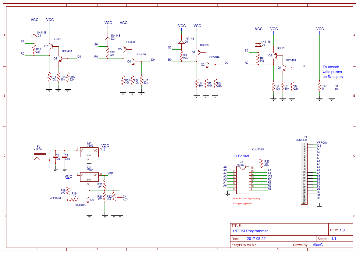
As you can see the 74S571 is a 4 bit data word while Yann's PROM is an 8 bit data word.
Here is my strip-board design for the PROM Programmer:
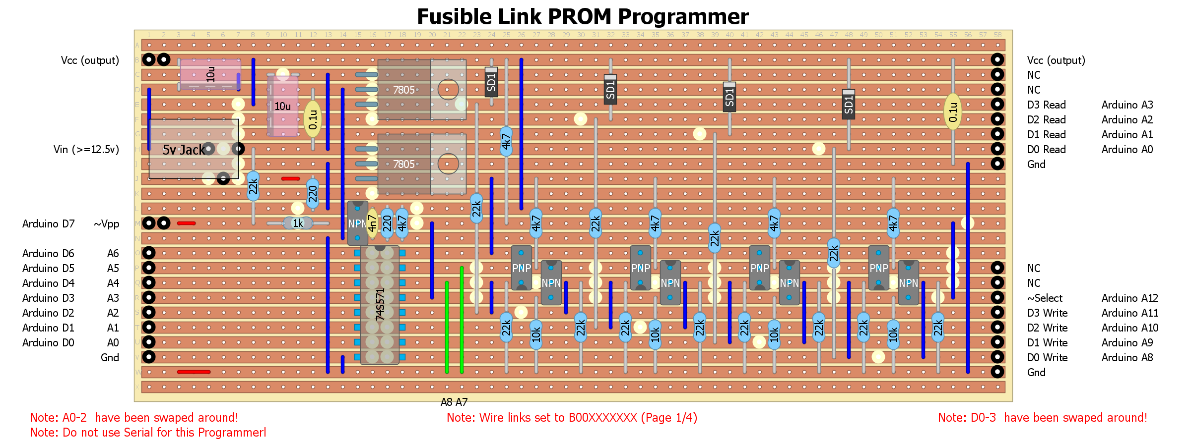
Note the Arduino Pin assignments will change for the published PROM Programmer code.
The top voltage regulator is for the 5v logic, the bottom regulator is for the programming voltage pulse. The green links are for different PROM pages, as only 128 bytes are (currently) programmable at a time.
The main problems with this design is the voltage regulators get hot if the programmer is left plugged into the power supply. The second problem is the need to connect (i.e. wire up) the programmer to an Arduino each time it is used. Better is a Nano was integrated into the design.
The Programmer Code
I rewrote the PROM Programmer code. It is pretty hard to write code that has to work the first time! But this code is better. It reads the PROM code first and they you have the option to burn either the high or low nimble:
// PROM Programmer:
//   This code programs the LOW nibble of "ROM" data to the 74S571 PROM.
//   The "ROM" data is in the source code.
//   A factory PROM is all LOWs and the Programmer writes HIGHs on bit at a time.
//   The programmer has pull up resistors on VPP and /CS for safety.
//   After the PROM has been programmed the LED will blink slowly if successful (1s on/1s off).
//   If if unsuccessful the the LED will blink quickly (0.1s on/0.1s off).
//
//   Programmer connections:
//     D0  <-> TX
//     D1  <-> RX
//     D2  <-> PROM A0
//     D3  <-> PROM A1
//     D4  <-> PROM A2
//     D5  <-> PROM A3
//     D6  <-> PROM A4
//     D7  <-> PROM A5
//     D8  <-> PROM D0
//     D9  <-> PROM D1
//     D10 <-> PROM D2
//     D11 <-> PROM D3
//     D12 <-> PROM A6
//     D13 <-> D13 (LED)
//     A0  <-> PROM Sense D0
//     A1  <-> PROM Sense D1
//     A2  <-> PROM Sense D2
//     A3  <-> PROM Sense D3
//     A4  <-> PROM VPP (MUST STAY HIGH FOR 5V)
//     A5  <-> PROM /CS (ACTIVE LOW)
//     A6  <-> A6 (NANO ONLY - ANALOG READ ONLY)
//     A7  <-> A7 (NANO ONLY - ANALOG READ ONLY)
// Set bytes (nibbles) to read
const int bytes=128;
#include <avr/pgmspace.h>
// Here is the "ROM" data (only the low nibble is used)
const byte PROGMEM ROM[bytes] = {
  0XDD, 0XFF, 0X8D, 0X9D, 0XDD, 0X00, 0X7D, 0X8D,
  0X9D, 0XA7, 0XB8, 0XC9, 0X2A, 0X3B, 0X4C, 0X0A,
  0X1B, 0X00, 0X1C, 0X00, 0XDD, 0XFF, 0X1D, 0XDD,
  0X0F, 0XED, 0XDD, 0X0A, 0X5D, 0XDD, 0XF9, 0X0D,
  0XDD, 0XFF, 0X1D, 0X1D, 0X00, 0XDD, 0X20, 0XED,
  0X05, 0X50, 0X00, 0XDD, 0X1D, 0XED, 0X07, 0X12,
  0X11, 0X51, 0X02, 0X11, 0X05, 0X71, 0XA7, 0X08,
  0X13, 0X11, 0X51, 0X03, 0X11, 0X05, 0X81, 0XB8,
  0X09, 0X14, 0X11, 0X51, 0X04, 0X11, 0X05, 0X91,
  0XC9, 0XDD, 0X09, 0XFD, 0X21, 0X00, 0X00, 0X00,
  0X00, 0X00, 0X00, 0X00, 0X00, 0X00, 0X00, 0X00,
  0X00, 0X00, 0X00, 0X00, 0X00, 0X00, 0X00, 0X00,
  0X00, 0X00, 0X00, 0X00, 0X00, 0X00, 0X00, 0X00,
  0X00, 0X00, 0X00, 0X00, 0X00, 0X00, 0X00, 0X00,
  0X00, 0X00, 0X00, 0X00, 0X00, 0X00, 0X00, 0X00,
  0X00, 0X00, 0X00, 0X00, 0X00, 0X00, 0X00, 0X00
};
void ReadPROM(byte bytes)
{
  byte Data;
  byte Addr;
  // Make sure controls are set for read
  PORTC|= B00010000; // Set VPP HIGH
  PORTC&= B11010000; // Set /CS LOW and D0-3 LOW
  for (Addr=0;Addr<bytes;Addr++) {
    // Set Address
    PORTD=(PORTD&B00000011)|(Addr<<2);
    PORTB=(PORTB&B11101111)|((Addr>>2)&B00010000);
    delayMicroseconds(5); // Wait for data to settle (>3 us)
    // Read the PROM
    Data=PINC&B00001111;
    if (Addr%16==0) {
      Serial.println();
      if (Addr==0) {
        Serial.print("00:");
      } else {
        Serial.print(Addr,HEX);
        Serial.print(":");
      }
    }
    Serial.print(" ");
    Serial.print(Data,HEX);
    delay(5); // enough time for 4 characters per loop
  }
  // Make sure controls are set to off
  PORTC|= B00110000; // Set VPP HIGH (5V) and /CS HIGH (deselected)
}
void setup() {
  // INITIALISE PORTS
  // PortC XX/VSSSS
  //       XXCP3210
  //       XXSP
  PORTC|= B00110000; // Set VPP and /CS HIGH
  DDRC &= B11110000; // Set S0-3 as inputs
  DDRC |= B00110000; // Set VPP and /CS as outputs
  // Bit   76543210
  // PortD AAAAAART
  //       543210XX
  DDRD |= B11111100; // Set A0-5 as outputs
  PORTD&= B00000011; // Set A0-5 LOW
  // PortB XXLADDDD
  //       XXE63210
  //       XXD
  DDRB |= B00111111; // Set LED, A6 and D3-0 as outputs
  PORTB&= B11000000; // Set LED, A6 and D3-0 LOW
  // Set Serial
  Serial.begin(9600);
}
int  Delay=1000;
void loop() {
  byte CPort;
  byte Data;
  byte Addr;
  byte Nibble=0;
  byte BitNo;
  byte Pass;
  byte Verify;
  char Ans;

  delay(100);
  Serial.println("Welcome to the 74S571 PROM Programmer.");
  delay(100);
  Serial.println("Please power up the PROM Programmer now.");

  delay(100);                                  // Wait for output buffer to clear
  Serial.print("First read the PROM (y/n)?");  // Message
  while (Serial.available()) Serial.read();    // Flush input buffer
  while (!Serial.available());                 // Wait for response
  Ans=Serial.read();                           // Get answer
  if ((Ans=='y')||(Ans=='Y')) {
    // Read PROM
    ReadPROM(bytes);
    delay(100);
    Serial.println();
    Serial.println("PROM read done.");
  } else {
    delay(100);
    Serial.println();
    Serial.println("PROM read aborted.");
  }

  // PROM Programmer
  delay(100);
  Serial.println();
  Serial.print("Ready to program the PROM (y/n)?");
  while (Serial.available()) Serial.read();
  while (!Serial.available());
  Ans=Serial.read();
  if ((Ans=='y')||(Ans=='Y')) {
    delay(100);
    Serial.println();
    Serial.print("Write high or low nimble of ROM data (h/l)?");
    while (Serial.available()) Serial.read();
    while (!Serial.available());
    Ans=Serial.read();
    if ((Ans=='H')||(Ans=='h')) Nibble=4;

    // Make sure controls are set off (VPP and /CS HIGH)
    PORTC|=B00110000;
    for (Addr=0;Addr<bytes;Addr++) {
      // Read the data to be programmed
      Data=pgm_read_byte(ROM+Addr);
      PORTD=(PORTD&B00000011)|(Addr<<2);
      PORTB=(PORTB&B11101111)|((Addr>>2)&B00010000);
      delayMicroseconds(1);

      for (BitNo=Nibble;BitNo<Nibble+4;BitNo++) {
        if (((Data>>BitNo)&B00000001)==1) {

          // Set Data bit
          PORTB=(PORTB&B11110000)|(B00000001<<(BitNo-Nibble));
          delayMicroseconds(1);
          // Write bit cycle
          for (Verify=0;Verify<2;Verify++) {
            // Write the bit
            for (Pass=0;Pass<10;Pass++) {
              PORTC&=B11101111;      // Bring up VPP to 10.5v (active low)
              delayMicroseconds(1);
              PORTC&=B11011111;      // Select chip (active low)
              delayMicroseconds(10);
              PORTC|=B00100000;      // Unselect chip
              PORTC|=B00010000;      // Bring down VPP to 5v
              delayMicroseconds(33); // Maximum duty cycle is 25%
            }
            // Verify
            PORTB&=B11110000;        // Set D0-3 LOW (off)
            PORTC&=B11011111;        // Make /CS low (select)
            delayMicroseconds(5);    // Wait for data to settle
            // Read the PROM
            CPort=PINC;
            if ((Data&(B00000001<<BitNo+Nibble))==(CPort&(B00000001<<BitNo+Nibble))) break;
          }

          // Post verify bit write
          PORTB=(PORTB&B11110000)|(B00000001<<(BitNo-Nibble));
          delayMicroseconds(1);
          for (Pass=0;Pass<5;Pass++) {
            PORTC&=B11101111;      // Bring up VPP to 10.5v (active low)
            delayMicroseconds(1);
            PORTC&=B11011111;      // Select chip (active low)
            delayMicroseconds(10);
            PORTC|=B00100000;      // Unselect chip
            PORTC|=B00010000;      // Bring down VPP to 5v
            delayMicroseconds(33); // Maximum duty cycle is 25%
          }
        }
      }
    }
    // Check Read PROM
    delay(100);
    Serial.println();
    Serial.print("Post programmed PROM read");
    ReadPROM(bytes);

    // Make sure controls are set to off
    PORTC|= B00110000; // VPP HIGH (5V) and /CS HIGH (deselected)
    delay(100);
    Serial.println();
    Serial.println("PROM write done.");
  } else {
    delay(100);
    Serial.println();
    Serial.print("PROM write aborted.");
  }
  delay(100);
  Serial.println();
  Serial.println("PROM Programmer done.");

  while(true) {
    digitalWrite(13,HIGH);
    delay(Delay);
    digitalWrite(13,LOW);
    delay(Delay);
  }
}
Here are two runs changing the nimble 0x4C:
Welcome to the 74S571 PROM Programmer.
Please power up the PROM Programmer now.
First read the PROM (y/n)? y
00: D F D D D 0 F D D F B D A B C A
10: B 0 D 0 D F D D F F D A D D F D
20: D F D D 0 D 2 F 5 5 0 D D F 7 3
30: 1 5 2 1 5 7 F 8 3 1 5 3 1 5 9 B
40: 9 5 1 5 4 1 5 9 D D 9 F 0 0 0 0
50: 0 0 0 0 0 0 0 0 0 0 0 0 0 0 0 0
60: 0 0 0 0 0 0 0 0 0 0 0 0 0 0 0 0
70: 0 0 0 0 0 0 0 0 0 0 0 0 0 0 0 F
PROM read done.
Ready to program the PROM (y/n)? y
Write high or low nimble of ROM data (h/l)? l
Post programmed PROM read
00: D F D D D 0 F D D F B D A B C A
10: B 0 D 0 D F D D F F D A D D F D
20: D F D D 0 D 2 F 5 5 0 D D F 7 3
30: 1 5 2 1 5 7 F 8 3 1 5 3 1 5 9 B
40: 9 5 1 5 4 1 5 9 D D 9 F 1 0 0 0
50: 0 0 0 0 0 0 0 0 0 0 0 0 0 0 0 0
60: 0 0 0 0 0 0 0 0 0 0 0 0 0 0 0 0
70: 0 0 0 0 0 0 0 0 0 0 0 0 0 0 0 F
PROM write done.
PROM Programmer done.
Welcome to the 74S571 PROM Programmer.
Please power up the PROM Programmer now.
First read the PROM (y/n)? y
00: D F D D D 0 F D D F B D A B C A
10: B 0 D 0 D F D D F F D A D D F D
20: D F D D 0 D 2 F 5 5 0 D D F 7 3
30: 1 5 2 1 5 7 F 8 3 1 5 3 1 5 9 B
40: 9 5 1 5 4 1 5 9 D D 9 F 1 0 0 0
50: 0 0 0 0 0 0 0 0 0 0 0 0 0 0 0 0
60: 0 0 0 0 0 0 0 0 0 0 0 0 0 0 0 0
70: 0 0 0 0 0 0 0 0 0 0 0 0 0 0 0 F
PROM read done.
Ready to program the PROM (y/n)? y
Write high or low nimble of ROM data (h/l)? h
Post programmed PROM read
00: D F D D D 0 F D D F B D A B C A
10: B 0 D 0 D F D D F F D A D D F D
20: D F D D 0 D 2 F 5 5 0 D D F 7 3
30: 1 5 2 1 5 7 F 8 3 1 5 3 1 5 9 B
40: 9 5 1 5 4 1 5 9 D D 9 F 3 0 0 0
50: 0 0 0 0 0 0 0 0 0 0 0 0 0 0 0 0
60: 0 0 0 0 0 0 0 0 0 0 0 0 0 0 0 0
70: 0 0 0 0 0 0 0 0 0 0 0 0 0 0 0 F
PROM write done.
PROM Programmer done.
AlanX
Discussions
Become a Hackaday.io Member
Create an account to leave a comment. Already have an account? Log In.
Hi, great project. I started building this programmer. BUt I have a question about the two voltage regulators 7805. Can you tell me if the outputs are tied together. And how does this exactly work to switch from 5V to 12V. I assume that once the voltage goes to 12V t, the hole circuit gets this voltage.
Are you sure? yes | no