 Radu Motisan
February 12, 2013: The Atmega128 board got a power supply, for both 5V and 3V. The latter is for the Bluetooth module and one of the GPS modules.
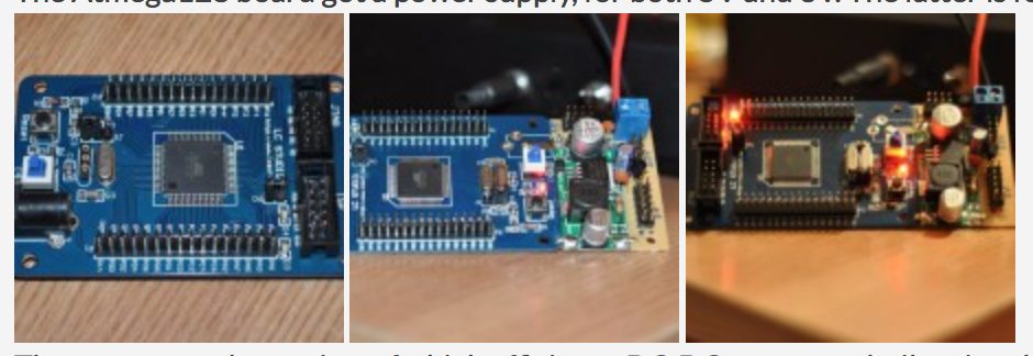 The power supply consists of a high efficiency DC-DC converter built using the LM2596 IC. There are plenty of such converters available on Ebay for just a few bucks. I replaced the pot with a fixed 1KO resistor, so the converter would put out a fixed 5V voltage. The 3V is obtained using two L78L33 's. The power boards where fixed to the Atmega128 board.
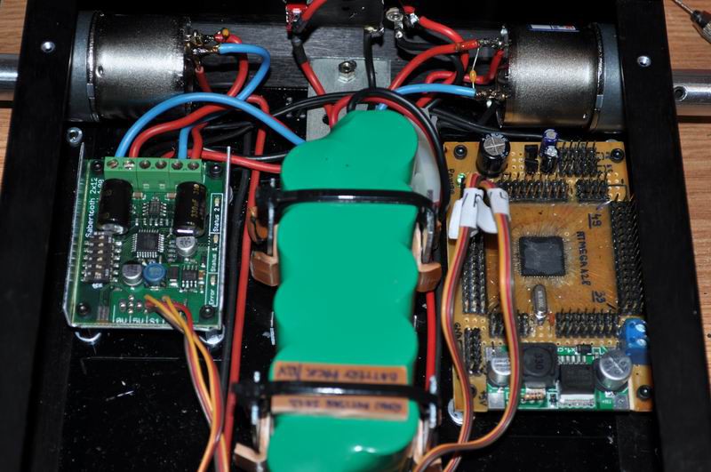
February 18, 2013: New Atmega128 board, with pin connectors including power and gnd to make connections easier. The microcontroller board has been mounted to the robot's platform. The Sabertooth 2X12 has also been mounted. Thick wires link the h-bridge and the motors.
Discussions
Become a Hackaday.io Member
Create an account to leave a comment. Already have an account? Log In.