 Rob Englebright
STEM Sussex Big Bang Fair requires loud, bright attractions to engage with the visiting students.
ST3Mbot meets those needs. He started life as an old flip top bin, that had a nice Chrome lid (or head). I chopped the bin in half with a dremel, and welded a square frame of 20x40 ERW steel on which to mount the legs.
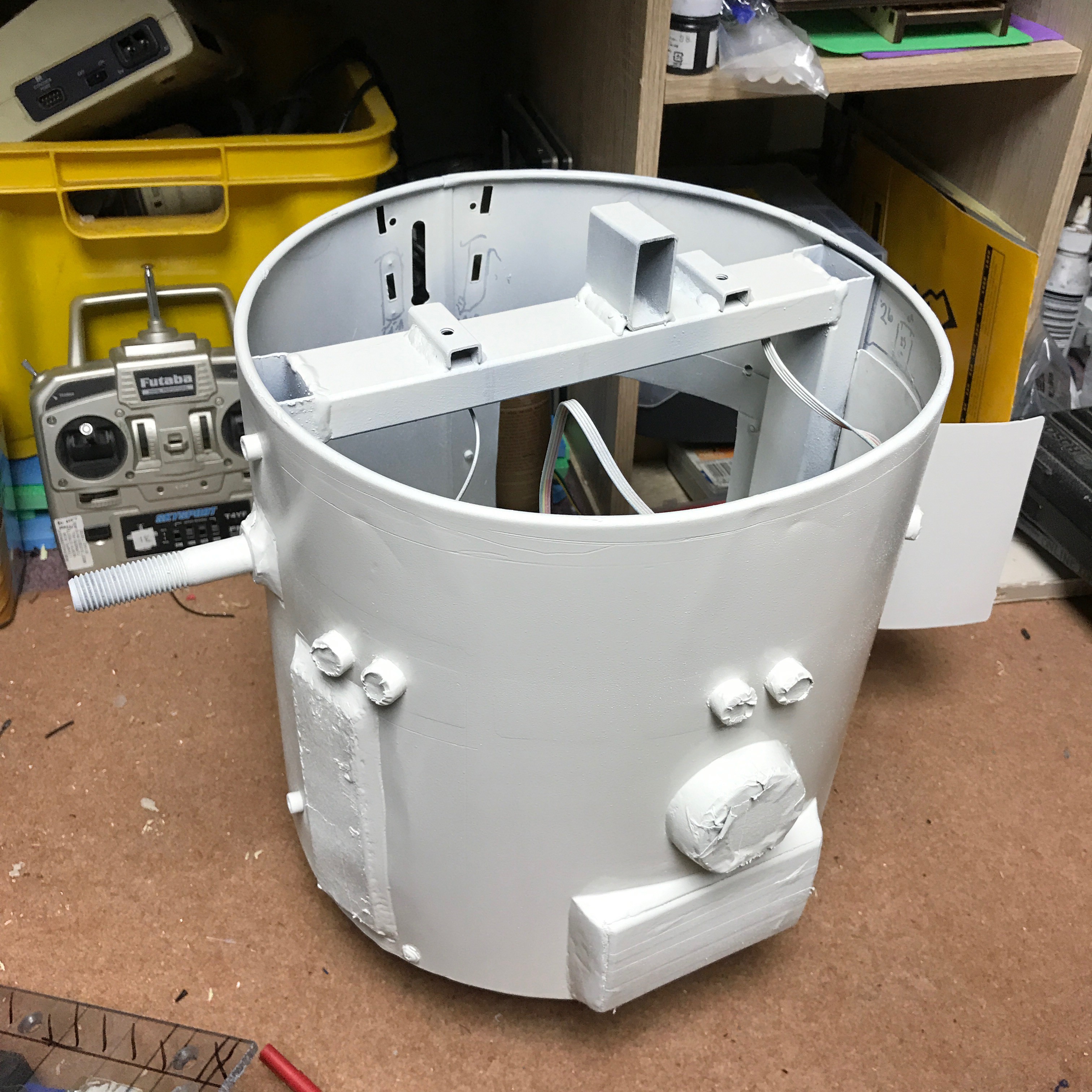
I cut holes to mount 3 sr04 ultrasonic units, a thermal printer and a grill for the speaker. I welded on a couple of M16 bolts to the sides to hold the legs. The legs were made of old library shelving, 50x50 box steel. Welded into a T to hold the drive wheels. For the neck I reinforced the plastic bin base with MDF, and welded a couple of bolt brackets to the steel frame to hold it in place. Originally I was going to have one R2 style "eye", but sketches looked good with a couple of Neopixel eyes so that's what I did.
// NeoPixel Ring simple sketch (c) 2013 Shae Erisson
// released under the GPLv3 license to match the rest of the AdaFruit NeoPixel library
// Set as Leonardo 5V 16Mhz - Device is 5V 16MHz Pro micro clone
#include <Adafruit_NeoPixel.h>
#ifdef __AVR__
#include <avr/power.h>
#endif
// set pin out and LED no
#define PIN 2
#define NUMPIXELS 12
Adafruit_NeoPixel pixels = Adafruit_NeoPixel(NUMPIXELS, PIN, NEO_GRB + NEO_KHZ800);
//set delay in microseconds
int delayval = 100;
void setup() {
pixels.begin(); // This initializes the NeoPixel library.
}
void loop() {
// first NeoPixel is 0, second is 1
for(int i=0;i<NUMPIXELS;i++){
// pixels.Color takes RGB values, from 0,0,0 up to 255,255,255
pixels.setPixelColor(i, pixels.Color(25,0,0));
pixels.show();
delay(delayval);
}
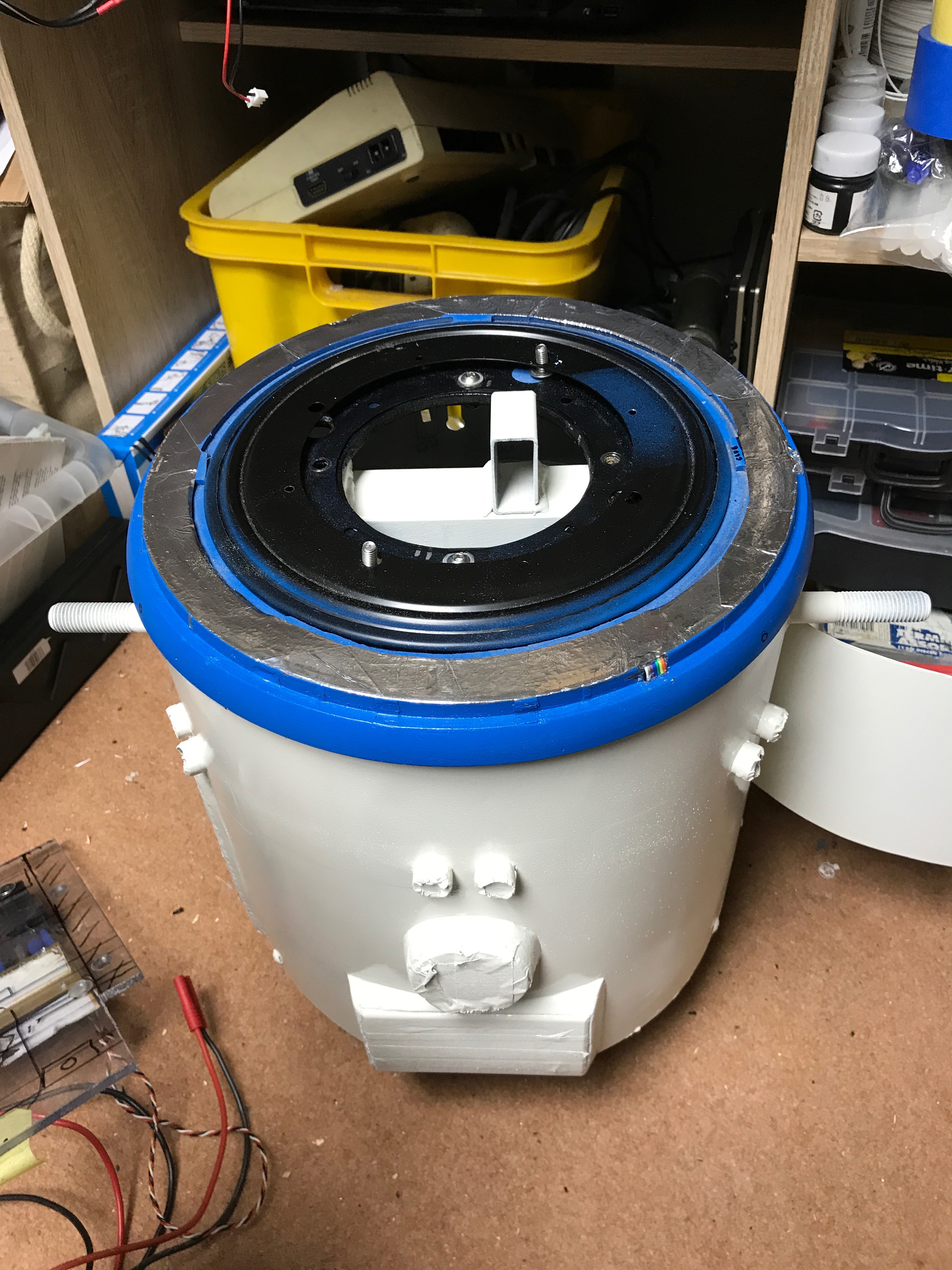
}I checked the R2 builders form for the best way to rotate the head, and it seems that a "lazy susan" easily bought from eBay is what most folk use. I fitted an MDF base mounted a couple of L brackets to bolt to the chrome head.
In the centre of the lazy susan I mounted an old servo I've had laying around since Technogames in 2000, the photo shows the original set- up, with a rigid mecano bar fixing the servo to the neck. Testing showed this was a problem, and I later rigged up a bungee cord to give a bit of slack in the system, as the original bar had no slack, and the servo was getting a bit hot.
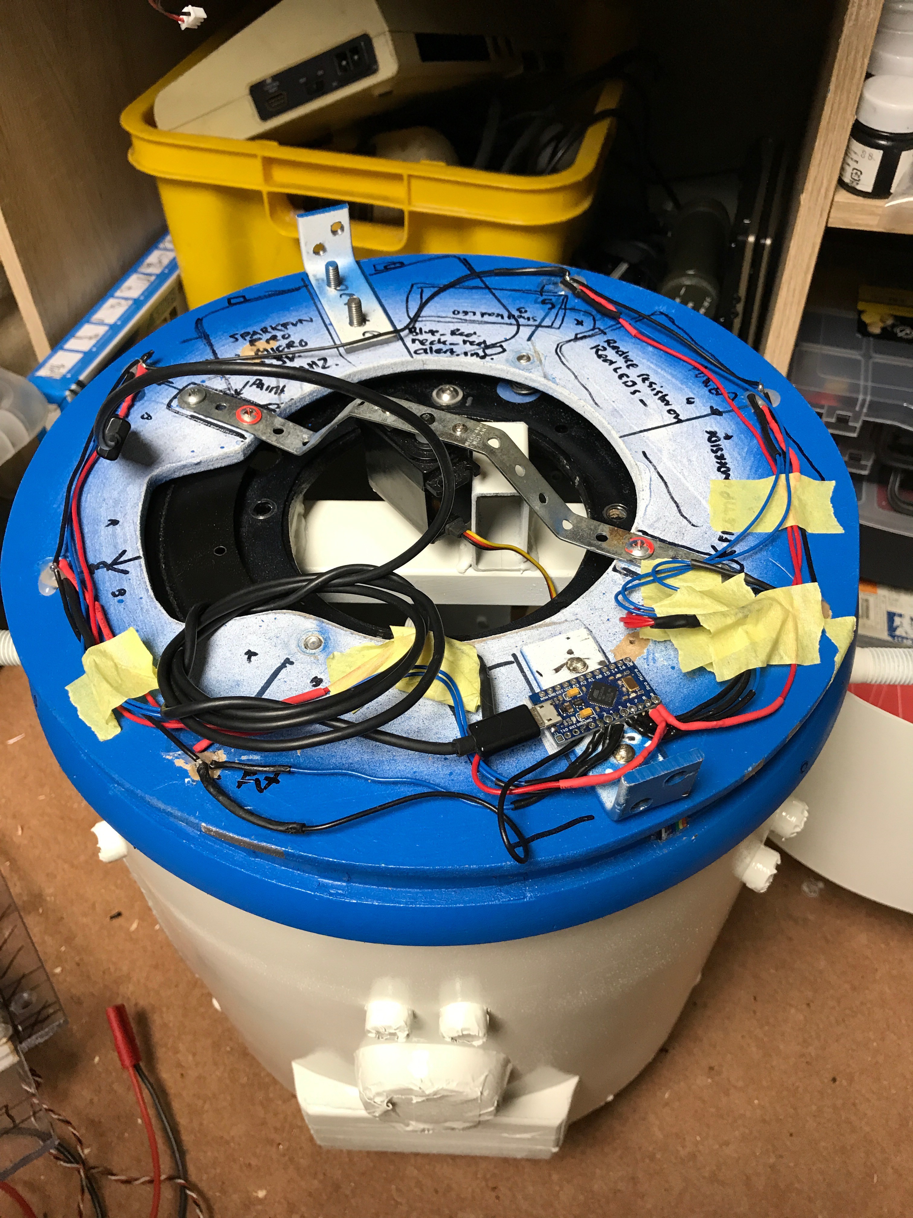
I used a trinket pro arduino for the servo which has enough power output to run the servo directly.
#include <Arduino.h>

/*
 HC-SR04 Ping distance sensor:
 VCC to arduino 5v
 GND to arduino GND
 sr04#01
 Echo to Arduino pin 7
 Trig to Arduino pin 8
 sr04#02
 Echo to Arduino pin 9
 Trig to Arduino pin 10
 sr04#03
  Echo to Arduino pin 11
 Trig to Arduino pin 12

 This sketch originates from Virtualmix: http://goo.gl/kJ8Gl
 Has been modified by Winkle ink here: http://winkleink.blogspot.com.au/2012/05/arduino-hc-sr04-ultrasonic-distance.html
 And modified further by ScottC here: http://arduinobasics.blogspot.com.au/2012/11/arduinobasics-hc-sr04-ultrasonic-sensor.html
 on 10 Nov 2012.
 Modified to turn head of ST3M droid using servo
 */

#include <Servo.h>

#define echoPin1 7 // Echo Pin
#define trigPin1 8 // Trigger Pin
#define echoPin2 9 // Echo Pin
#define trigPin2 10 // Trigger Pin
#define echoPin3 11 // Echo Pin
#define trigPin3 12 // Trigger Pin

Servo myservo;  // create servo object to control a servo
int maximumRange = 200; // Maximum range needed
int minimumRange = 0; // Minimum range needed
long duration1, duration2, duration3, distance;// Duration used to calculate distance
int servoposition = 0;//initialise servo


void setup() {
 Serial.begin (9600);
 pinMode(trigPin1, OUTPUT);
 pinMode(echoPin1, INPUT);
 pinMode(trigPin2, OUTPUT);
 pinMode(echoPin2, INPUT);
 pinMode(trigPin3, OUTPUT);
 pinMode(echoPin3, INPUT);
 myservo.attach(6);  // attaches the servo on pin 6 to the servo object

}

void loop() {

/* The following trigPin/echoPin cycle is used to determine the
 distance of the nearest object by bouncing soundwaves off of it.

 Add a loop to get closest object


 */

 digitalWrite(trigPin1, LOW);
 digitalWrite(trigPin2, LOW);
 digitalWrite(trigPin3, LOW);
 delayMicroseconds(2);

 digitalWrite(trigPin1, HIGH);
 digitalWrite(trigPin2, HIGH);
 digitalWrite(trigPin3, HIGH);
 delayMicroseconds(10);

 digitalWrite(trigPin1, LOW);
 digitalWrite(trigPin2, LOW);
 digitalWrite(trigPin3, LOW);
 duration1 = pulseIn(echoPin1, HIGH);
 duration2 = pulseIn(echoPin2, HIGH);
 duration3 = pulseIn(echoPin3, HIGH);

 //Calculate the distance (in cm) based on the speed of sound.
 //distance = duration/58.2;

 if (duration1 >= duration2 && duration1 >= duration3) {
  servoposition=0; //look left
  distance = duration1/58;
 } else if (duration3 >= duration1 && duration3 >= duration2) {
  servoposition=180; //look right
  distance = duration3/58;
 } else {
  servoposition =90;
  distance = duration2/58;
}

 if (distance >= maximumRange || distance <= minimumRange){
 /* Send a negative number to computer
 */
 Serial.println("-1");
 }
 else {
 /* Send the distance to the computer using Serial protocol */
 Serial.println(servoposition);
 myservo.write(servoposition);
 }

 //Delay 250ms before next reading.
 delay(250); //maybe longer lag to ensure head doesn't flit back and forth
}
The thermal printer runs some very simple code, when the big red button is pressed it picks a random STEM career and prints it out.
The last thing added to ST3Mbot was a drive system, he runs on 2 18v cordless drill motors with 100mm wheels directly connected, and 3D printed gearbox mounts. I'll go into more detail on this later. The speed controllers are old Electrons 30amp hobbies, and power from a Turing 14.8v battery. Initial excursions indicate that a few more volts would be useful, and the electrons should take unto 36v? to be honest I can't remember, and he is rather top heavy. The inverted T for the wheel base also means the drive motors have to work hard when turning so I've just fitted a pair of Omniwheels to the front. more later.