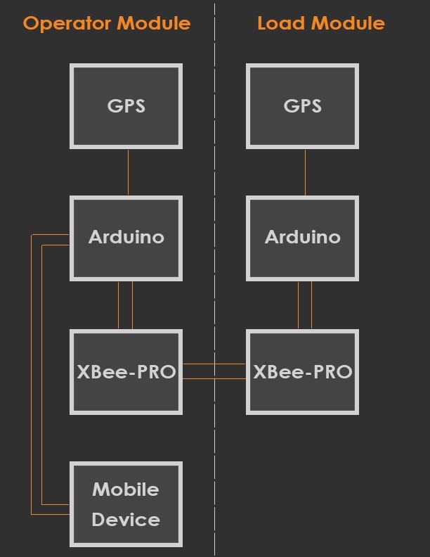
Hopefully the functional diagram picture I just added (below) is clear enough for most folks to understand:
There are two main modules -- 'Operator' and 'Load'.
The 'Operator' module is placed in the cab of the crane and interfaces with a mobile device (tablet, convertible PC, etc). It consist of
- a GPS device (to know where the center of the axis of rotation is roughly
- an XBee RF module to communicating remotely with the 'Load' module
- an Arduino Mini Pro for orchestrating the communications of the GPS and RF modules and finally
- a mobile device for visualizing all the data and providing alerts.
It should be clear that the GPS device simply sends data to the Arduino (as NMEA sentences). The Arduino then parses the sentences and extracts only the pertinent information. That information is then passed to the mobile device for viewing. Of course, viewing where the cab of your crane is in real time isn't all that helpful if you don't know the position of your load!
The 'Load' module is very similar to the 'Operator' module except that it doesn't need to pair with a mobile device. This module is physically clamped to the hoist line directly above the headache ball. The Arduino parses the data from the GPS module and sends it via RF (the XBee-PRO module) back to the 'Operator' module. All of this data is ultimately presented to the 'HoistManager' application to aid the crane operator in make more informed decisions about his hoist.
While I still have not yet nailed down the exact specifications around battery requirements, I envision this system will notify the operator when the battery level of the 'Operator' or 'Load' modules drops below an acceptable level, at which point the respective batteries must be recharged/replaced to continue optimal service.
Discussions
Become a Hackaday.io Member
Create an account to leave a comment. Already have an account? Log In.
Are you sure? yes | no