 Paul Kocyla
The idea of a Mach Effect Thruster is to use a relativistic effect to generate directional forces with the help of the action at a distance with the mass of the entire universe. Sounds esoteric, but math says it works, and NASA is funding it due to positive experiments.
Basic function (simple explanation):
If you charge a capacitor and accelerate it at the same time, its rest mass increases.
If you discharge it, it decreases.
You can push the capacitor when it´s "heavier" and pull it when it´s "lighter". It will result in a directional force. Conservation of momentum is not broken, because the inertia is meant to be a relativistic effect depending on the rest mass of the entire universe and the momentum is exchanged with this mass (the reason it´s called "MEGA" drive - Mach Effect Gravitaional Assist)
If you never heard about this thruster, you need to check out Wikipedia first before following my details:
https://en.wikipedia.org/wiki/Woodward_effect
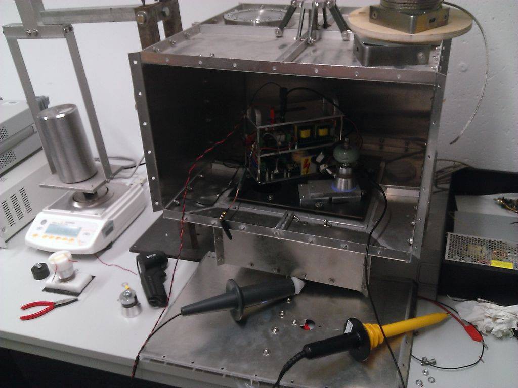
The Mach Effect thruster has been undergone several generations of heavy mutations during Woodward´s many years of research. The latest version is a PZT-only thruster, basically consisting of PZT disks and different solid blocks of aluminum and brass which are clamped together.
There was an early build where a PZT stack was shaking a capacitor directly - but it was discarded, because it seemed difficult to shake the cap with a controlled phase relation and a sufficient amplitude.
However, PZTs usually cannot be driven with high voltages (more few hundred volts) , but the Mach Effect forces seem to grow at square to the voltage. The PZT can be only run for a few seconds before getting very hot, so until now, the setups have been only made for a proof of the Mach Effect, not for a long duration firing thruster.
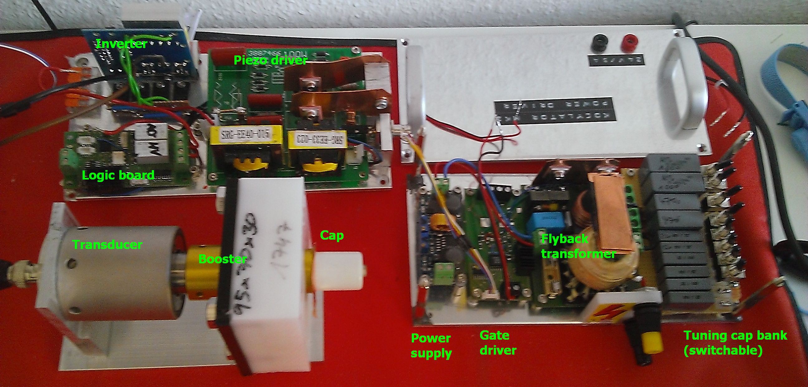
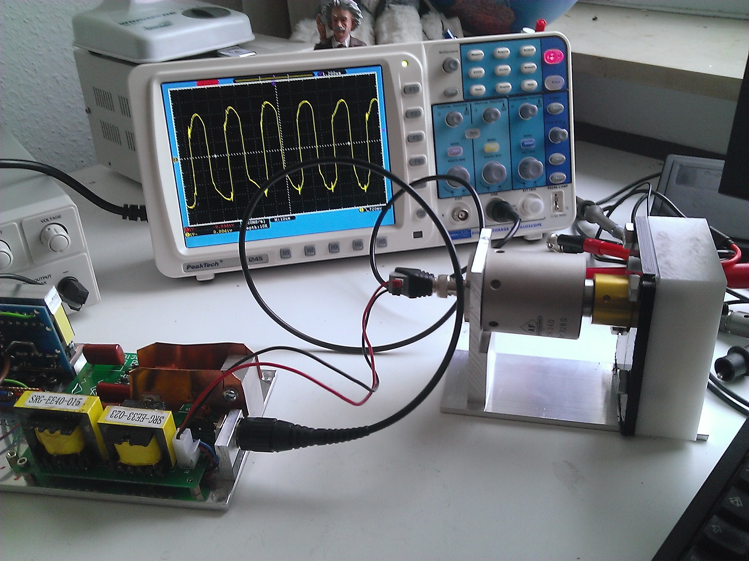
My approach uses a high voltage transformer to charge/discharge the cap and a tuned ultrasonic system to shake the cap.
First experiments have been done - new ideas and experiments are coming.
First tests have been driven with naive PZT/Cap combinations. The driver electronic had to be tested for hard vacuum conditions for upcoming tests.
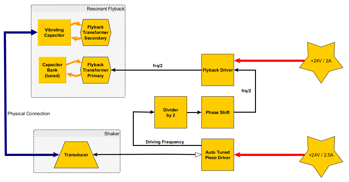
Here´s the system design:
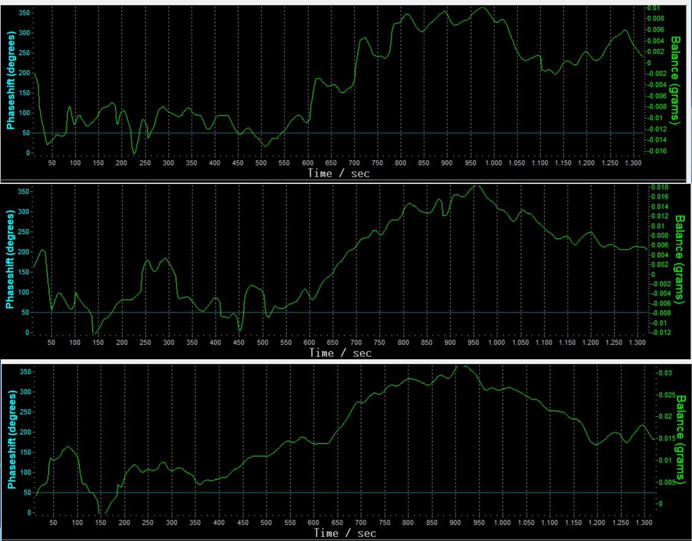
The power frequency of the capacitor is twice the frequency of the acceleration, so if you drive the transducer, you need to divide the frequency by two for driving the cap voltage. The phase has to be shifted to match the real world conditions. Phase shift occurs in the ultrasonic trasnmission of vibration to the cap, there are delays in the optocoupler which syncs the action of the transducer to the cap driver.
The challenge will be to make the cap shaking with a high amplitude. Due to the high sound frequency, it is not easy to achieve this.
I will use existing technologies used in ultrasonic welding to achieve this task.
Probably I will also mill and turn the acoustic parts by myself and document them on video.
BTW: Dresden University is developing their own thrusters - and I am thankful and proud to get support from them. In case I get the permission to do so, I will post material of real tests made on scale in hard vacuum with 20nN resolution.
There are several patents owned by Woodward regarding this technology.
Let´s make this dream of real space travel become true.
---
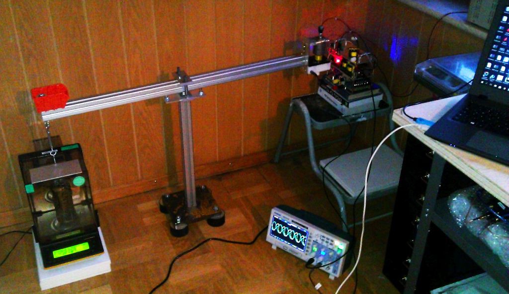
Currently (after the pre-tests) I am updating the electronics for the vacuum tests. We will be able to measure the amplitude of the shaken cap in realtime with a 200kHz sub-nanometer interferometer.
Meanwhile I am preparing a PZT/Cap combination optimized for a high amplitude, and I am eliminating some thermal issues which the pre-test revealed.
The main issue is: The intermediate circuit for providing the voltage to the ultrasonic driver is underdimensioned and gets too hot, electrolytic capacitors need to be either replaced or secured against bursting in vacuum.
Thermometers have to be installed on all critical systems.

 Josh Starnes
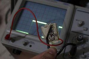
 Yann Guidon / YGDES
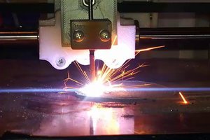
 Dominik Meffert
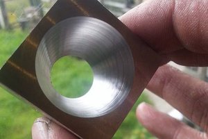
I've been working with ultrasonic transducers for many years. I've developed ultrasonic generators, also. I'd recommend stacking the PZT transducer wafers to increase power output and voltage tolerances. It's exciting technology with many capabilities!