 Dan DWRobotics
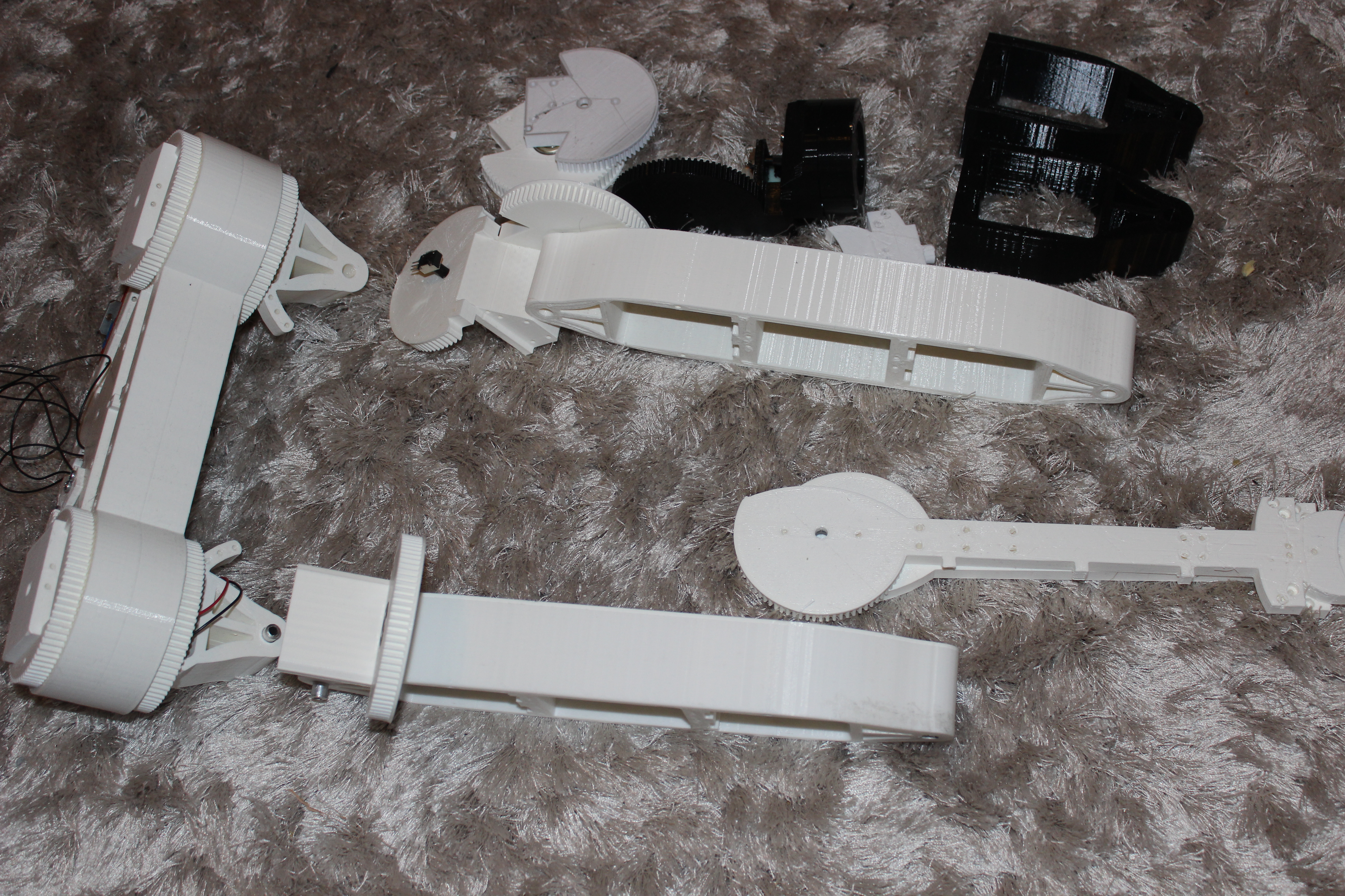
I am now feverishly printing parts, big parts. The above picture shows the new pelvis and the new 'Femurs' which are all now printed in one piece where they had previously been multiple parts bolted together. This reduces the complexity of the build and should ultimately lead to more rigidity in teh frame.
I've taken many of the drawbacks from the previous design and rectified them. The first thing that was annoying me about the previous design is that I tried to make human proportions to the joints, meaning I made the lower leg slightly shorter than the upper leg. This had the unintended consequence of making movements quite de-stablising to the whole structrue. My maths hasn't quite gotten to full body kinematics and so the new designs has these two parts of the leg as teh same length meaning moving between standing and crouching should be much smoother and less wobbly.
One of the other real key things I did was to redesign the cog ratios to give more torque and slower movements. This should have multiple benefits. Firstly, this machine is going to be STRONG. The extra torque is required as I am planning to add a torsoe, arms and a head. All will be fully motorised and so the extra weight will be substantial. The second major benefit to the new cog ratio should be smoother and slightly slower movements. Whilst I did like the fast response of the previous model, it was slightly too jerky and weirdly I actually need more mechanical movement at this stage, rather than human-like fast movements. I've gotten to know my new CR-10 and the extra build plate size really allows me to design much bigger parts, which is simplifying the build. Previously I had made small parts and bolted them together but the large print size and the success rate of the CR-10 means that I am not afraid to do big parts such as the pelvis below.
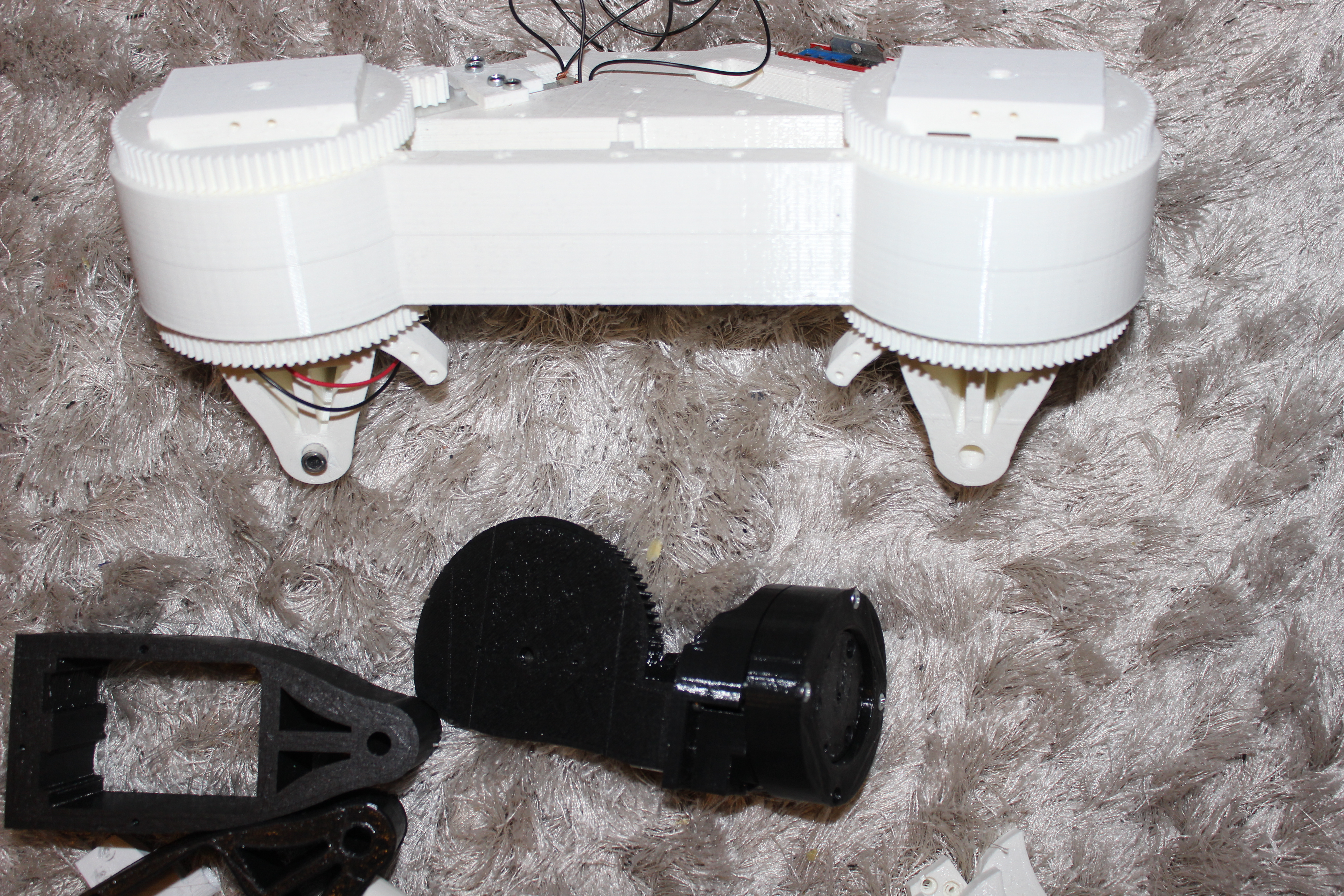
Above is the pelvis. Most of the parts don't have motors in yet. I am trying something totally bonkers and using the plastic on its own as a bearing. So the bearing is basically two massive printed barrels inside each other and the bearing relies on the plastic parts sliding against each other. This will work because the motors have a large amount of torque and the hip 'yaw' mechanism does not need a lot of torque. Previously I have inserted skateboard bearings into joints which is great for most applications, but for the hip 'yaw' or swivel mechanism this part needs to be very rigid as any 'give' in this joint is amplified along the length of the rest of the leg creating instability. Suffice to say, the joint is now incredibly rigid.

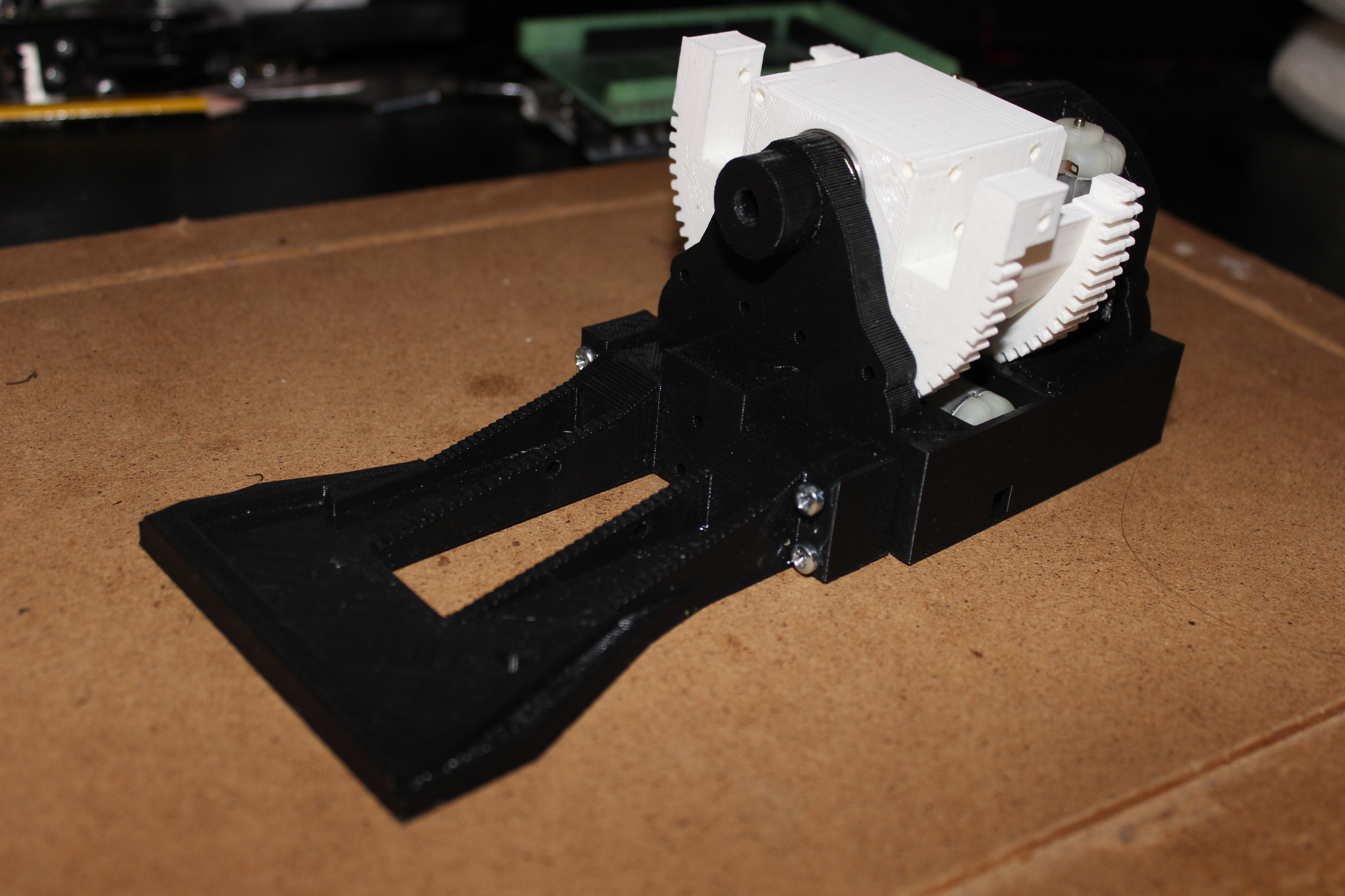
Then this is 'foot' mark II. It doesn't look like much, but I wish I could demonstrate how smooth and powerful the 'Ankle Roll' mechanism is. It is ridiculously strong, but when it is operating it could potentially need to resist the whole weight of the body when making any movements where teh body sways left and right, i.e. during walking, shifting the centre of balance between left and right foot. The toes are minimalist at the moment but the whole front section screws off so if I want to update those later I can. I am planning to attach four flat Force Sensitive Resistors to the base of the feet with some kind of rubber cover. This should provide some shock absortion and give a more uniform amount of force onto the FSR's so they are not just sensitive in their own spot.
I'm sure you all know, but I can't tell you how long it takes to design this many moving parts. Usually after a long day at work I will get home and start printing and work on the designs so it pretty tiring and I often need to force myself to get something substantial done. I still have a large amount to design, arms, hands and upper body.
Discussions
Become a Hackaday.io Member
Create an account to leave a comment. Already have an account? Log In.