 tomtibbetts
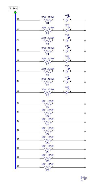
The W bus is the main bus for the SAP 1 computer. Data enters the bus from various sources then gets routed to various destinations. An example would be loading the A register from memory.
We build the W bus first because it will allow us to test register and other functions more easily as we assemble we assemble each module. This is because we have a direct way of entering data onto the bus through an 8 bit dip switch.
First we install eight red leds, the 330 ohm current limiting resistors and the 10K ohm pull down resistors.
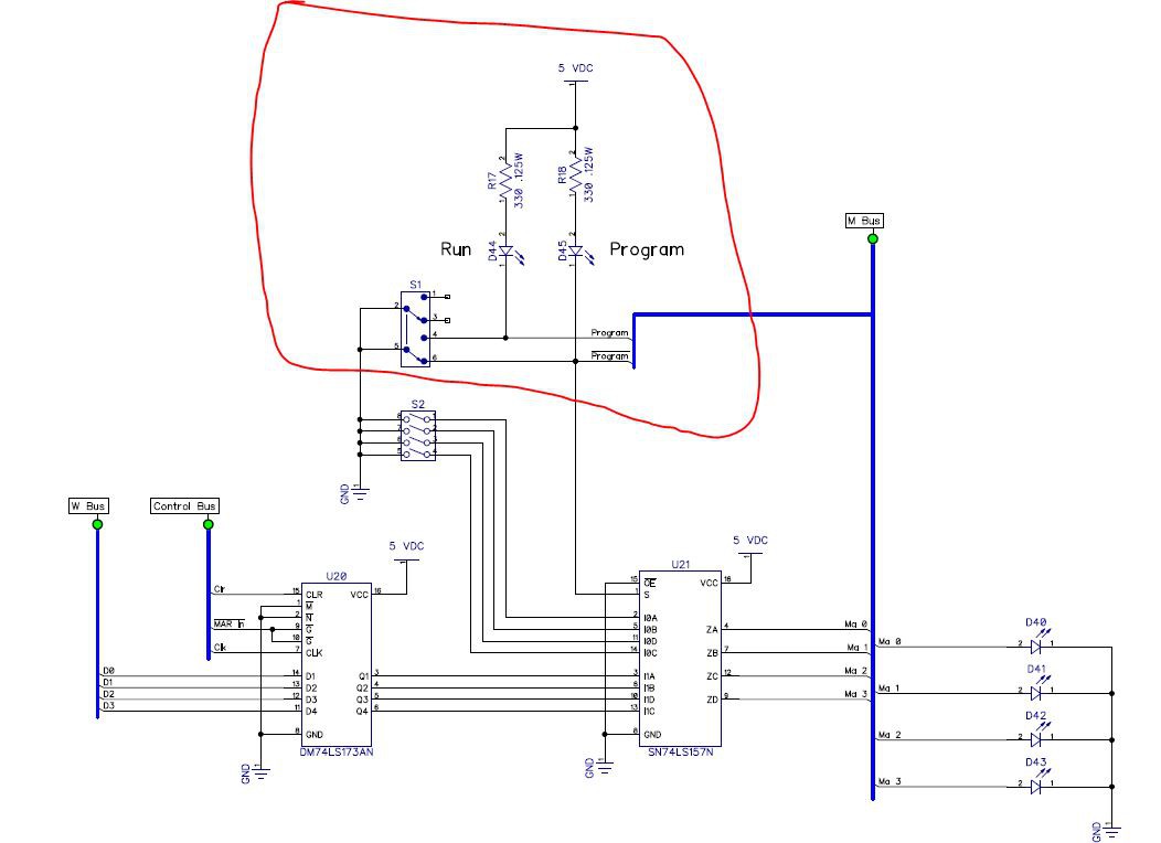
Next, we install S1, the DPDT slide switch, the green Run led and the red Pgm (program) led along with their 330 ohm resistors. These are indicated in the region marked in red below.
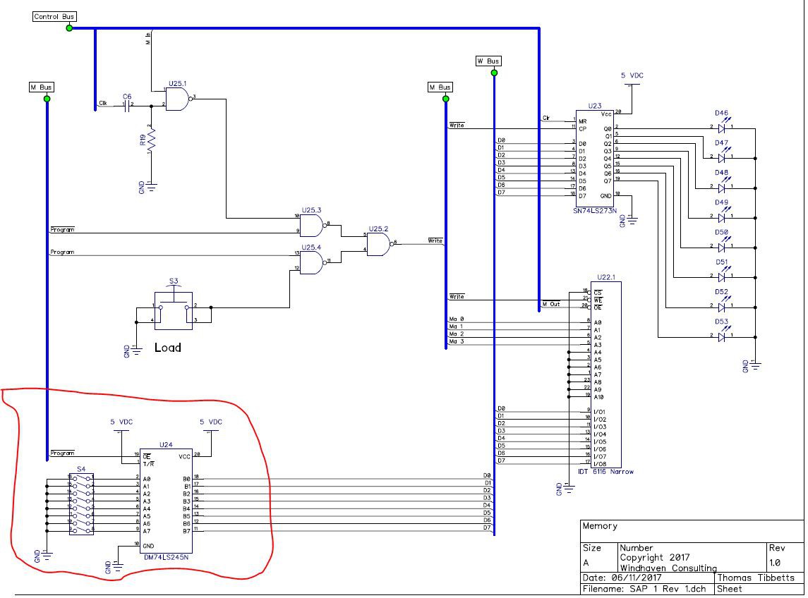
Next, we install S4, the 8 position dip switch. We install it upside down so that its position numbering runs from most significant bit on the left to the least significant bit on the right. Also, it needs to be upside down so that a logical one is when the switch is in the up position.
Finally, we install U24, the 74ls245 tri-state buffer. Whenever S1 is in the Pgm position, this buffer will be enabled allowing the data set by S4 to be placed on the W bus.
Discussions
Become a Hackaday.io Member
Create an account to leave a comment. Already have an account? Log In.