 tomtibbetts
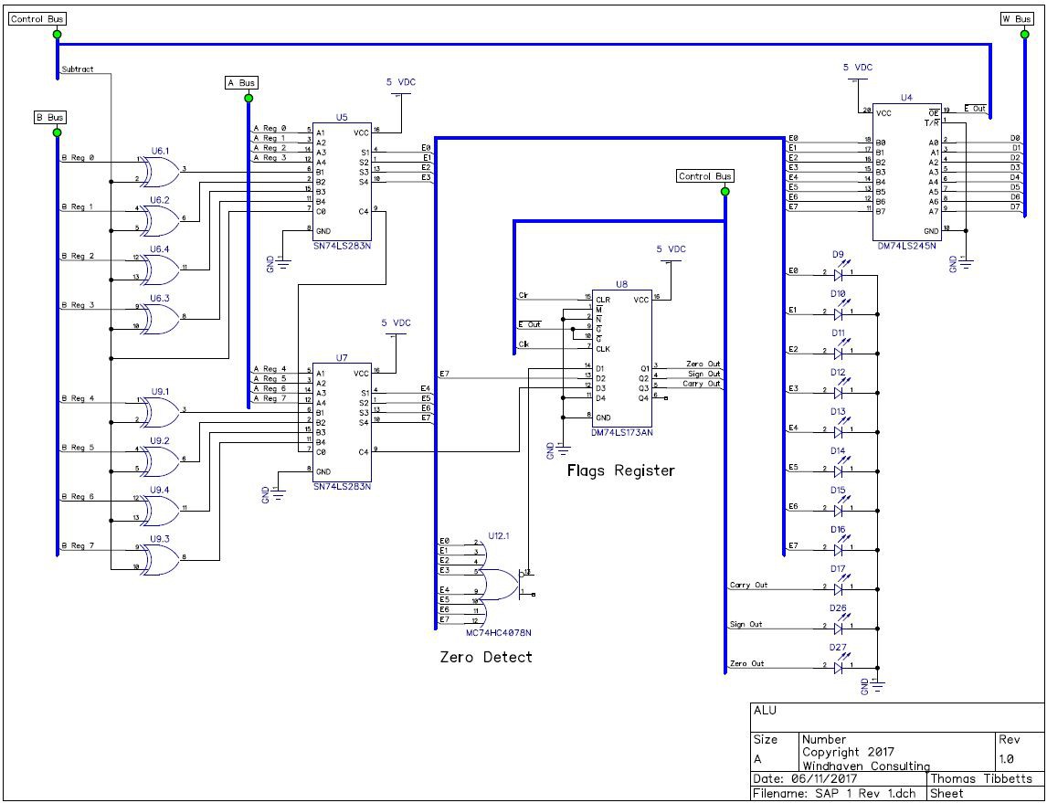
This next step involves building the ALU. The schematic is below.
Things of note that are not in Ben Eater's design include the 74HC4078 octal nor/or gate I use to detect a zero condition. Additionally, I added another 74ls173 quad latch to store the zero flag, the carry flag and the sign flag (goes to a one if the result is negative). These flags will be used later on when I need to do conditional jumping.
I did have issues with this build because of the forward voltage of the LEDs. In Ben Eater's design, the LEDs are wired directly from the logic outputs to ground without a current limiting resistor. You can get away with this in a lot of cases because most logic gates have built in 100 ohm resistors to limit current. The down side of this is that the most voltage you can get for a logic one is whatever the forward drop is of the LED, in my case about 1.9 volts. The problems this causes is that some of the logic inputs that follow have a hard time determining whether the signal is a logic one or a zero because, if you look at the specs sheets for these gates, you need a minimum of about 2.0 volts for a logic one. Additionally, the 74HC4078 is a cmos gate, so it needs about a minimum of, I think, 4.5 volts to register a logic one. So, consequently, I was never able to detect a non-zero state because the gate would never see a logic one. If you watch my video, you will notice that I removed the LEDs from the output of the 74ls283 adders because of this issue.
Other than the issue with the LEDs there were no changes to the board.
Discussions
Become a Hackaday.io Member
Create an account to leave a comment. Already have an account? Log In.