 Charles Galambos
The second version of the motor controller is based on a much more powerful ARM chip.
The design owes much to the open-source motor controller designs at http://vedder.se/2015/01/vesc-open-source-esc/, and https://hackaday.io/project/11583-odrive-high-performance-motor-control
If this wasn’t a project about learning and experimenting, ideally it would have been better to just use one of these designs. But they used shaft encoders, and/or didn’t seem optimised for driving motors at low speeds, at least at the time.
I did want to learn and experiment, and I wanted a new controller design which would drive bigger motors, with more precision, alongside other requirements such as CAN bus communication.
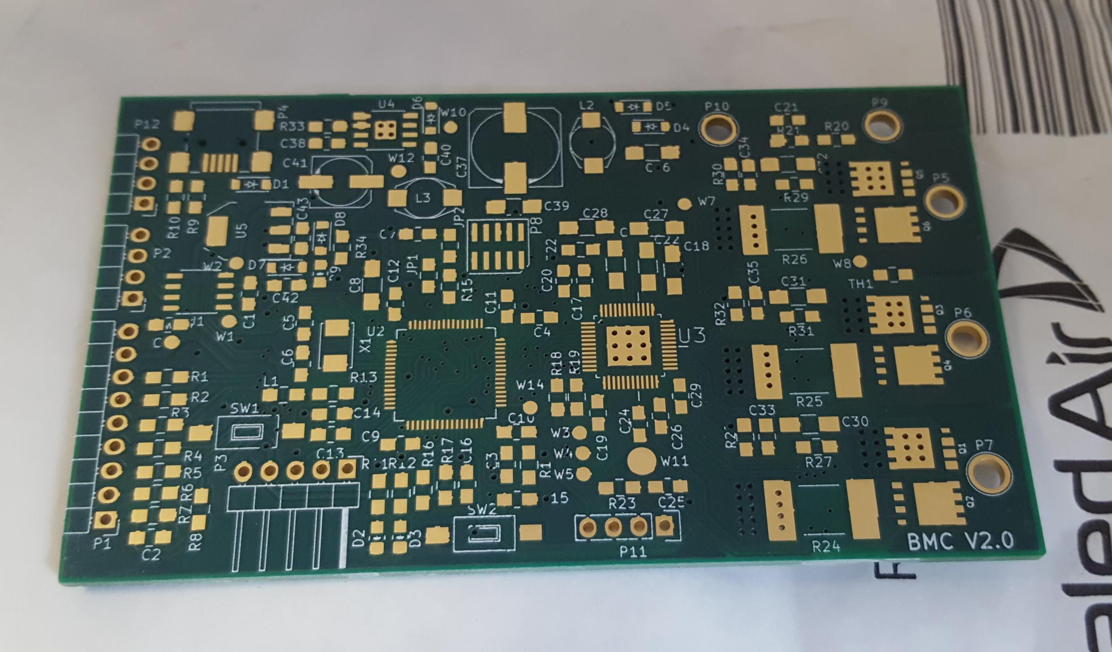
Here is the empty PCB as it arrived.
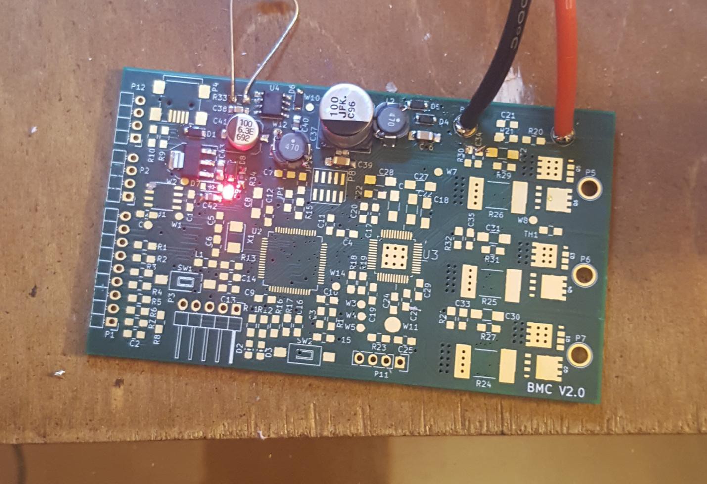
The first thing I did was populate the power supply, and check it was delivering the right voltages to the right places. This is much easier to do when nothing else is connected. As you can see the red power led is happily illuminated.
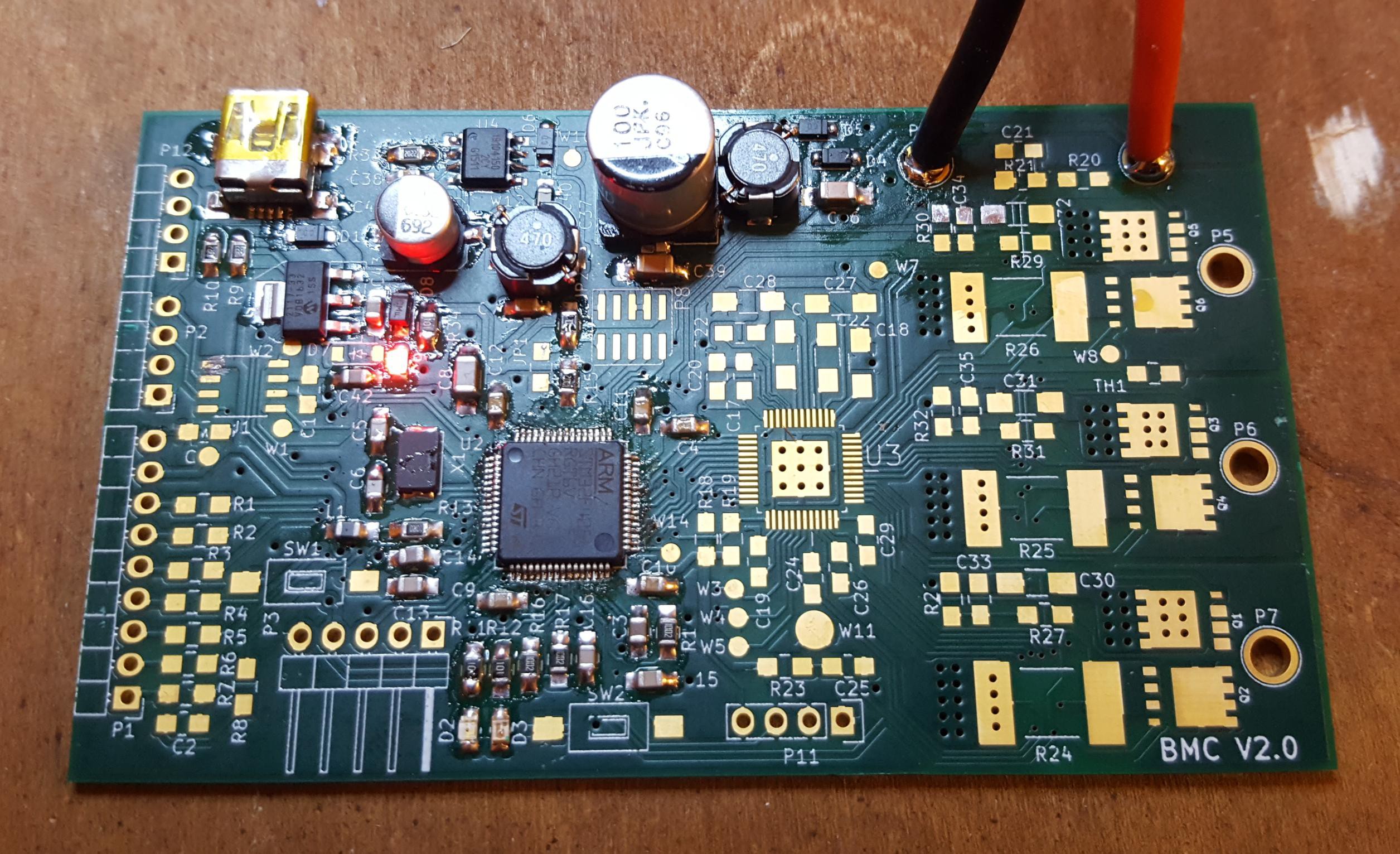
Next I populated the micro-controller. Things powered up, and no excess current draw, a good sign!
Next to hook it up to the programmer and see if we can get a LED to blink..
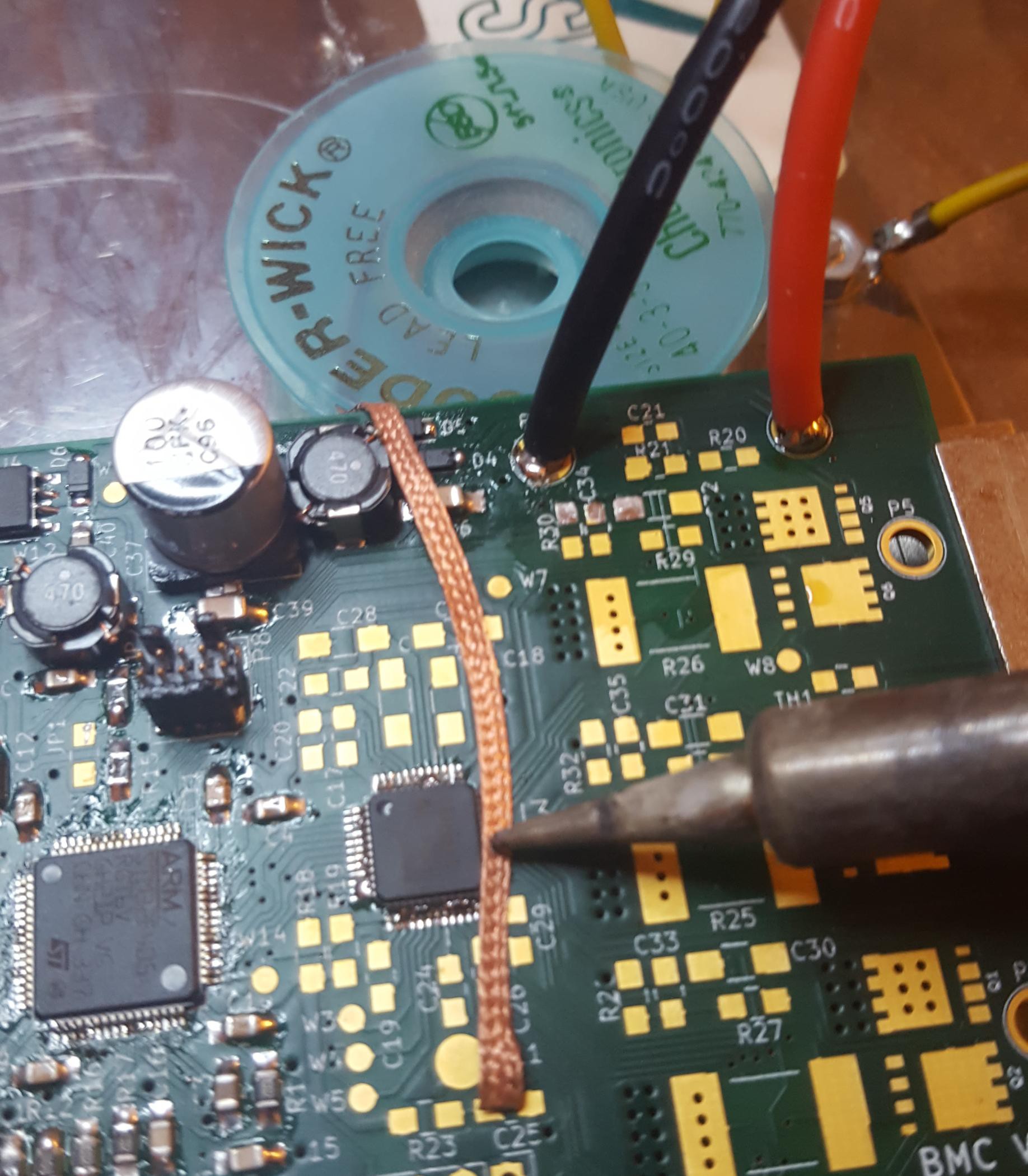
Next I fitted the rest of the electronic in the driver section. Soldering the large chips was tricky, essentially I ended up using as little solder paste as I could with a hot air gun. This would inevitable leave solder bridges between some of the pins of the chip, so I would then remove the excess solder away with solder wick.
The board with everything but a few connectors fitted.

Discussions
Become a Hackaday.io Member
Create an account to leave a comment. Already have an account? Log In.