 Ted Huntington
Open-Source Robot Building Kit and Development Environment
The main products in this robot building kit are:
1) Ethernet Modules (PCBs)
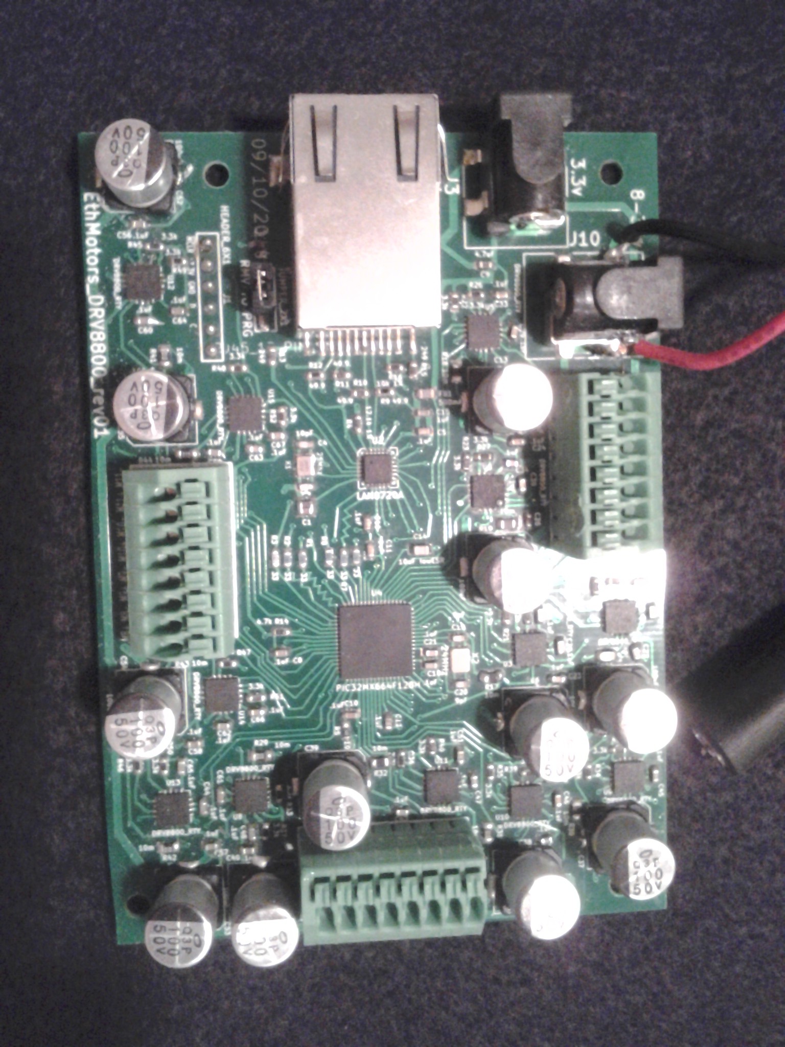
a) EthMotors - a Microchip PIC32 controls up to 12 motors (up to 2.8A each, using 12 Texas Instruments' DRV8800 motor drivers) over 100Mbit ethernet all on a single 100x72mm PCB. Uses 3.3V power supply, and an 8-36V motor power input. One to twelve motors can be connected individually into spring terminals. BOM cost: $64
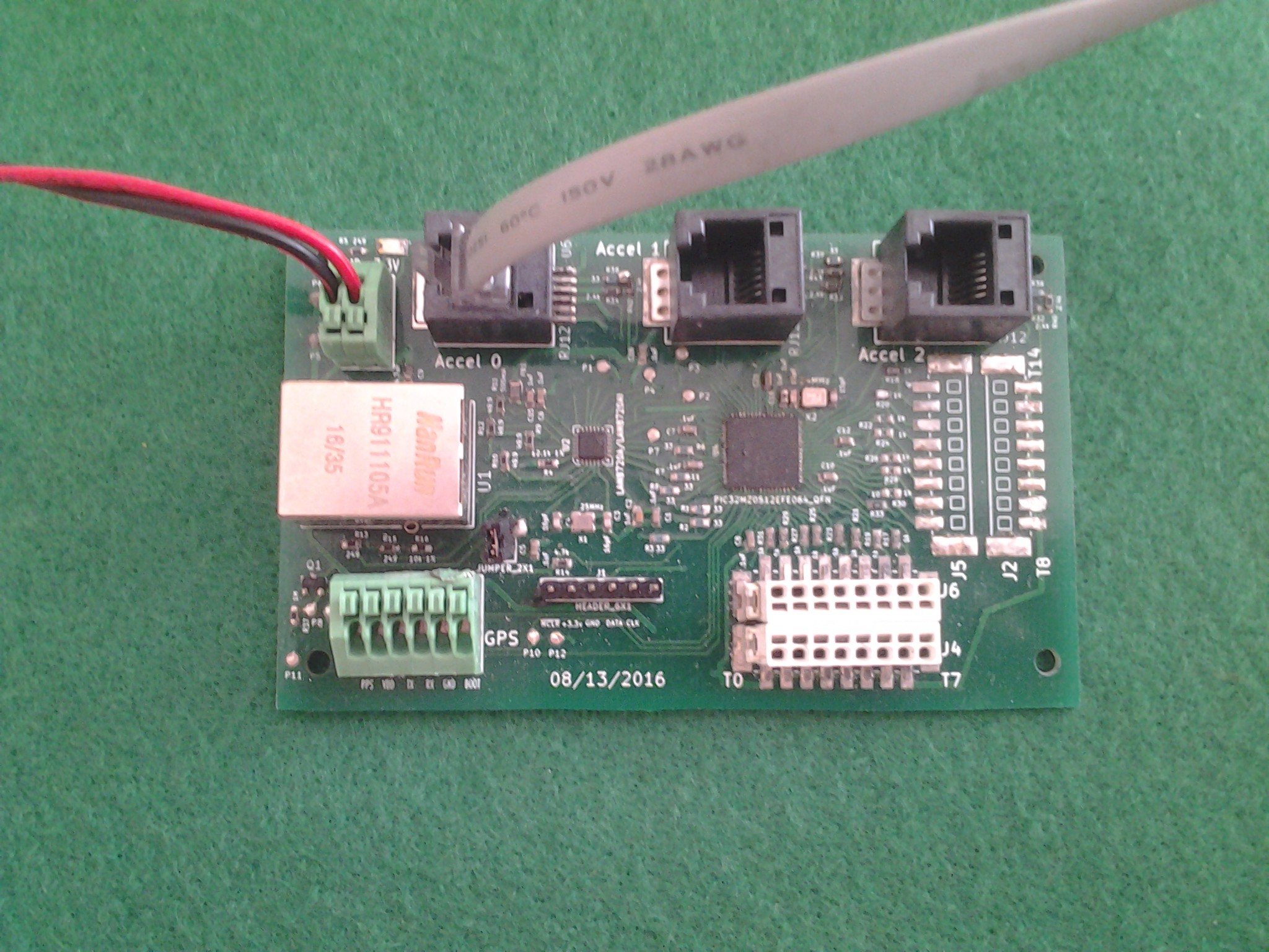
b) EthAccel - a microchip PIC32 can read from up to 3 Accelerometers+Gyroscopes (currently only InvenSense MPU-6050), and 15 touch sensors (ADC), at up to 100 samples/s. Uses 3.3V power supply. The two wires from a touch sensor are connected into top and bottom holes in the SMD spring terminals and read on the PIC32 ADC pins. Note that in this image 2 8-bit SMD spring terminals are not populated (and that the GPS code is currently not functional). BOM cost: $28
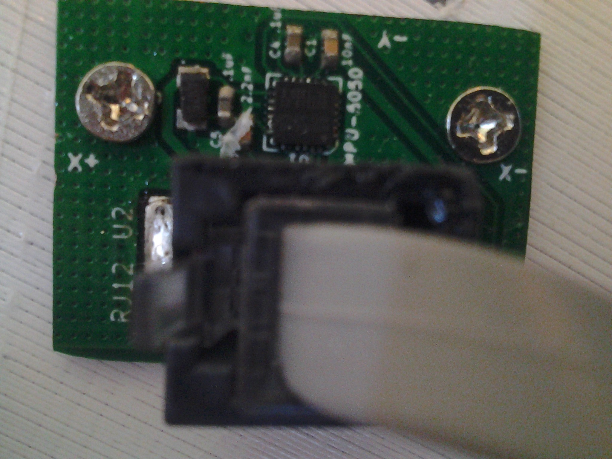
c) Accelerometer PCBs: This humble PCB houses an accelerometer+gyroscope IC, is fastened onto the robot part with screws, and connects to the EthAccel PCB using an RJ12 cable. BOM cost: $3
 |  |
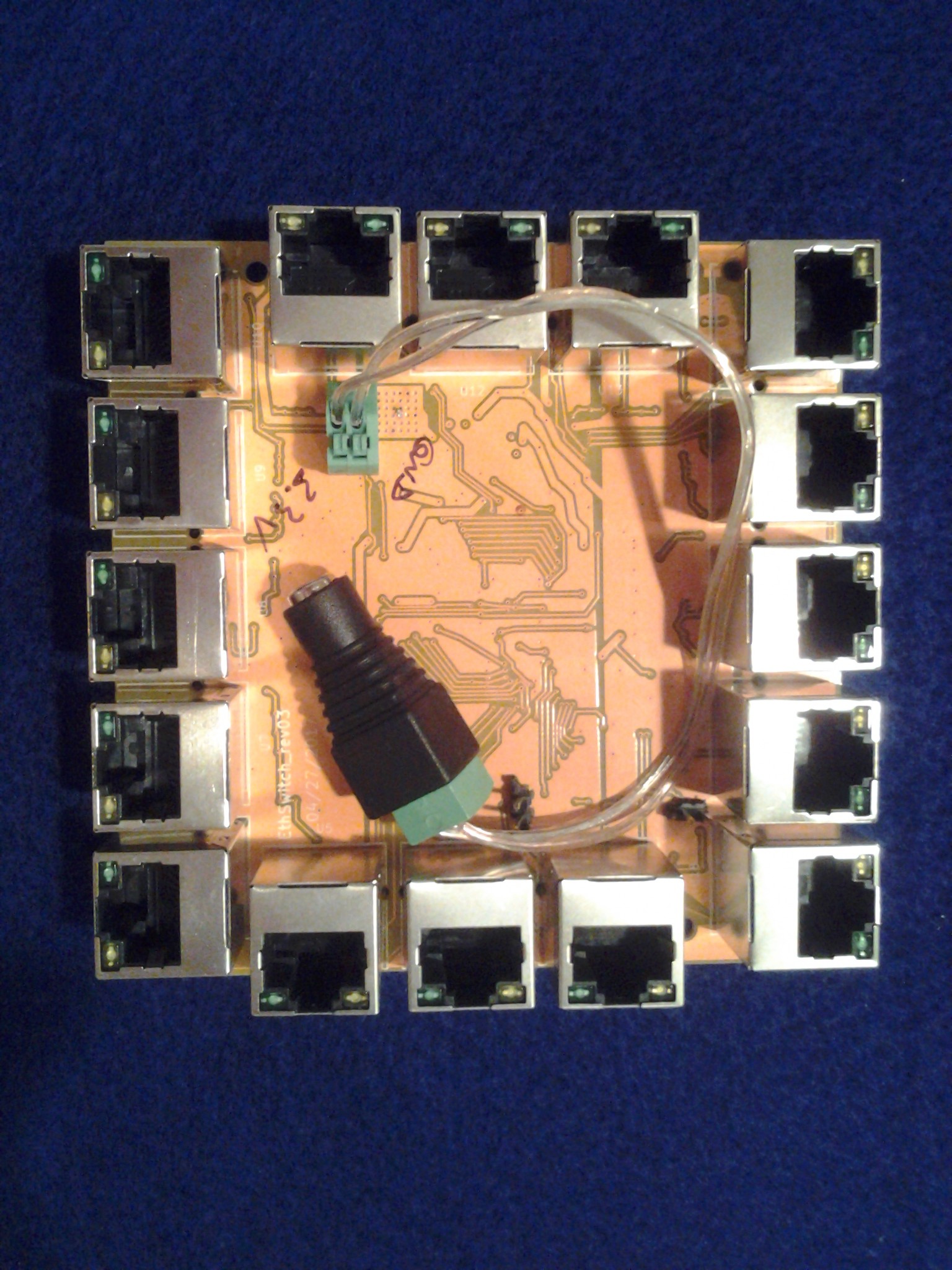
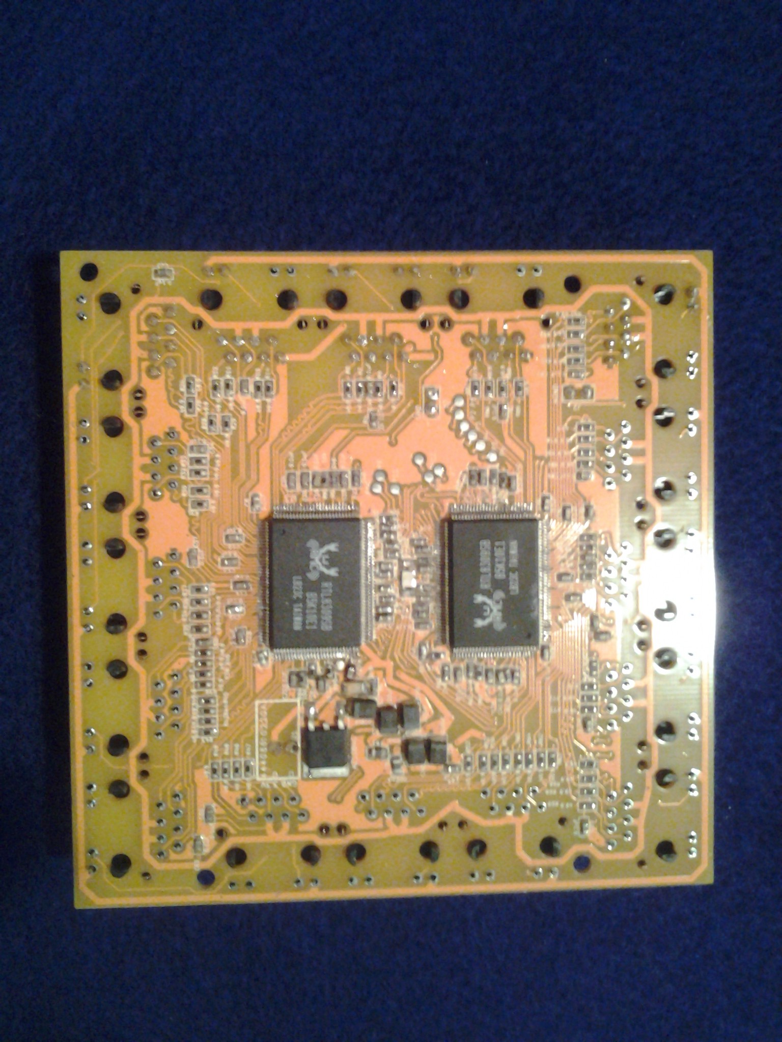
d) EthSwitch
1) 8-ports: A 100X60mm PCB that uses one (very low cost) Realtek RTL8309 IC to provide up to 8 10/100Mbit connections. Uses 3.3V power supply. BOM cost: $20
2) 16-ports: A 100X100mm PCB that uses two (very low cost) Realtek RTL8309 ICs to provide up to 16 10/100Mbit connections. Uses 3.3V power supply. BOM cost: $37
 |  |
2) Mechanical Products
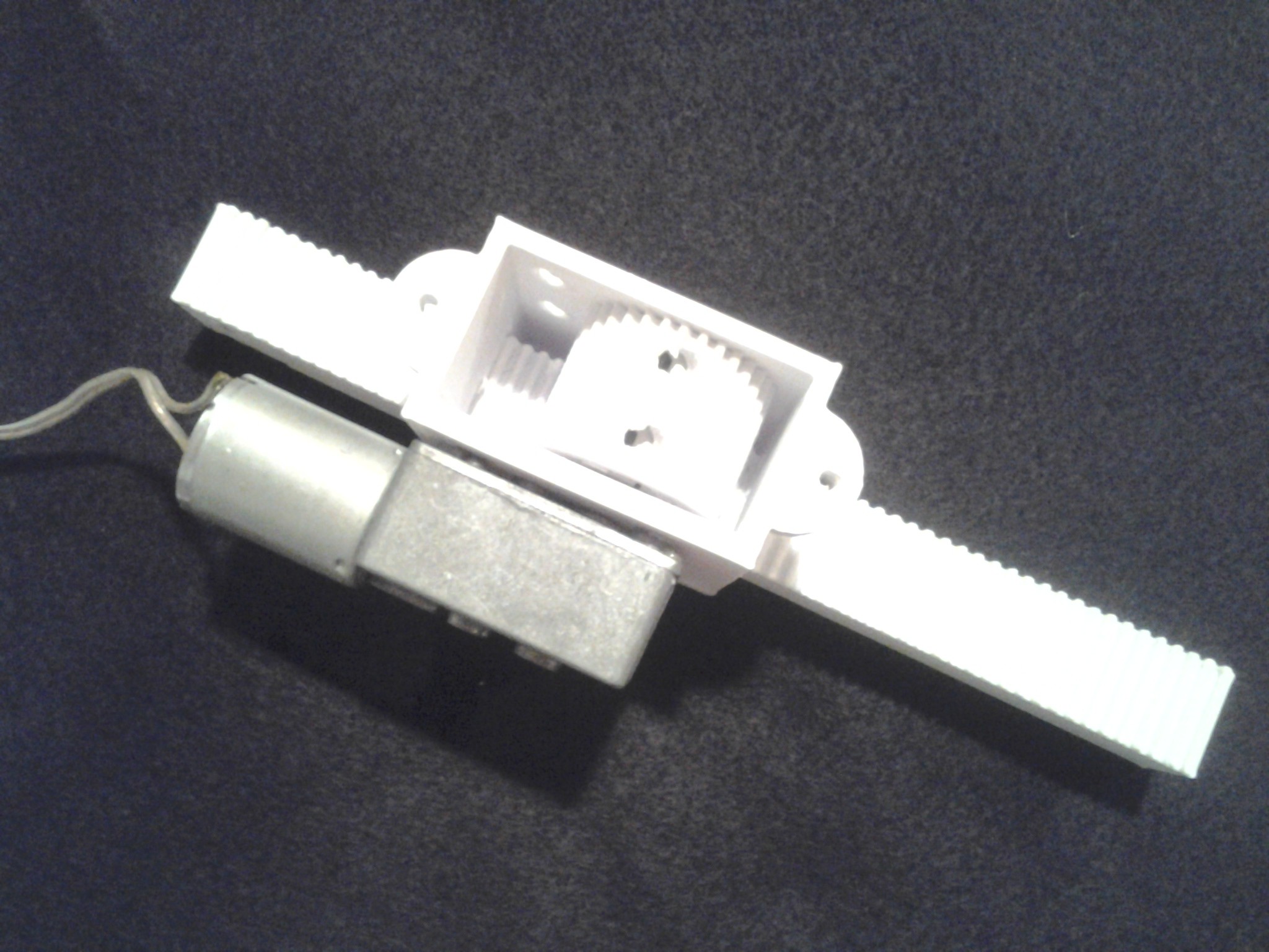
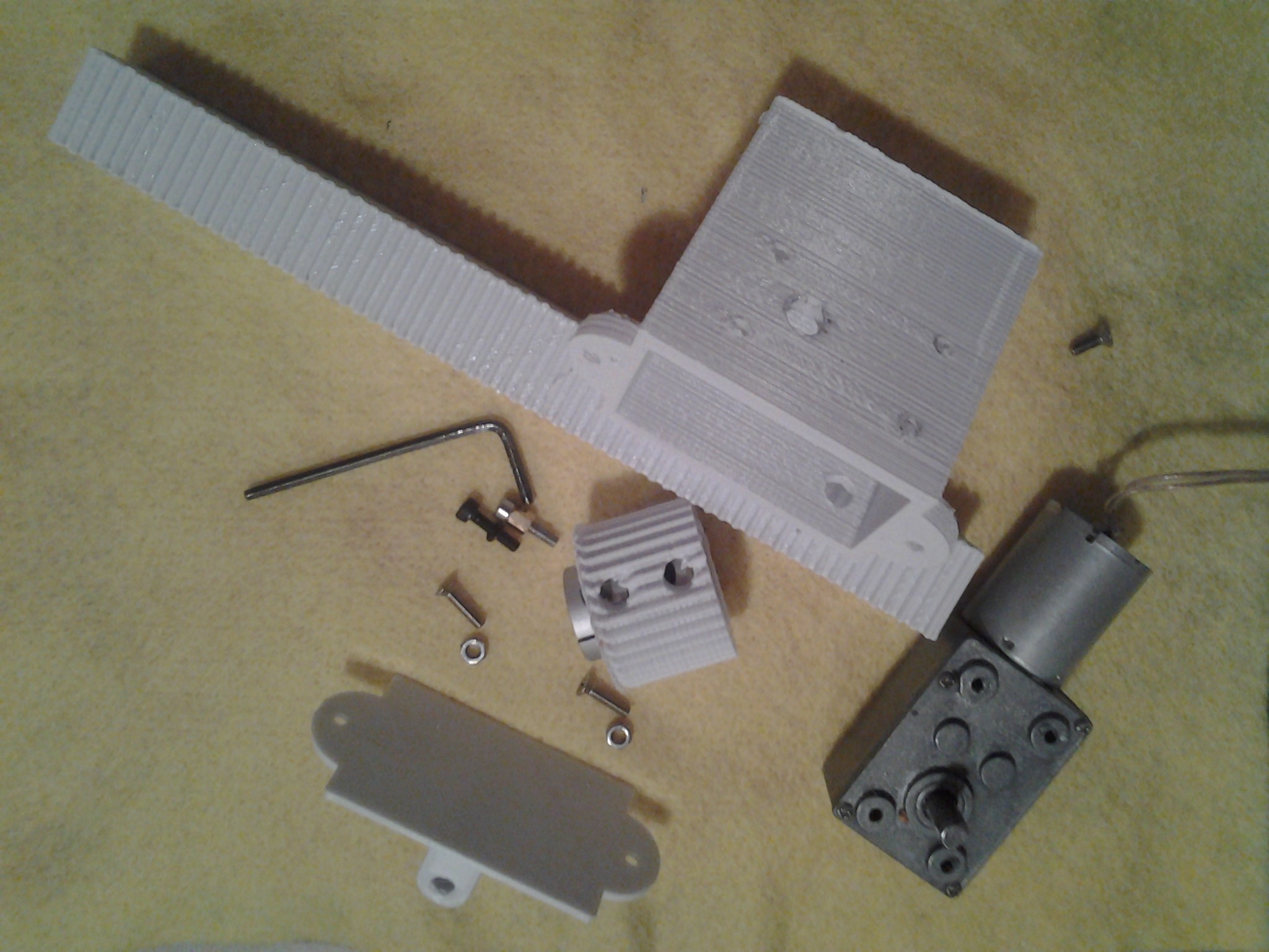
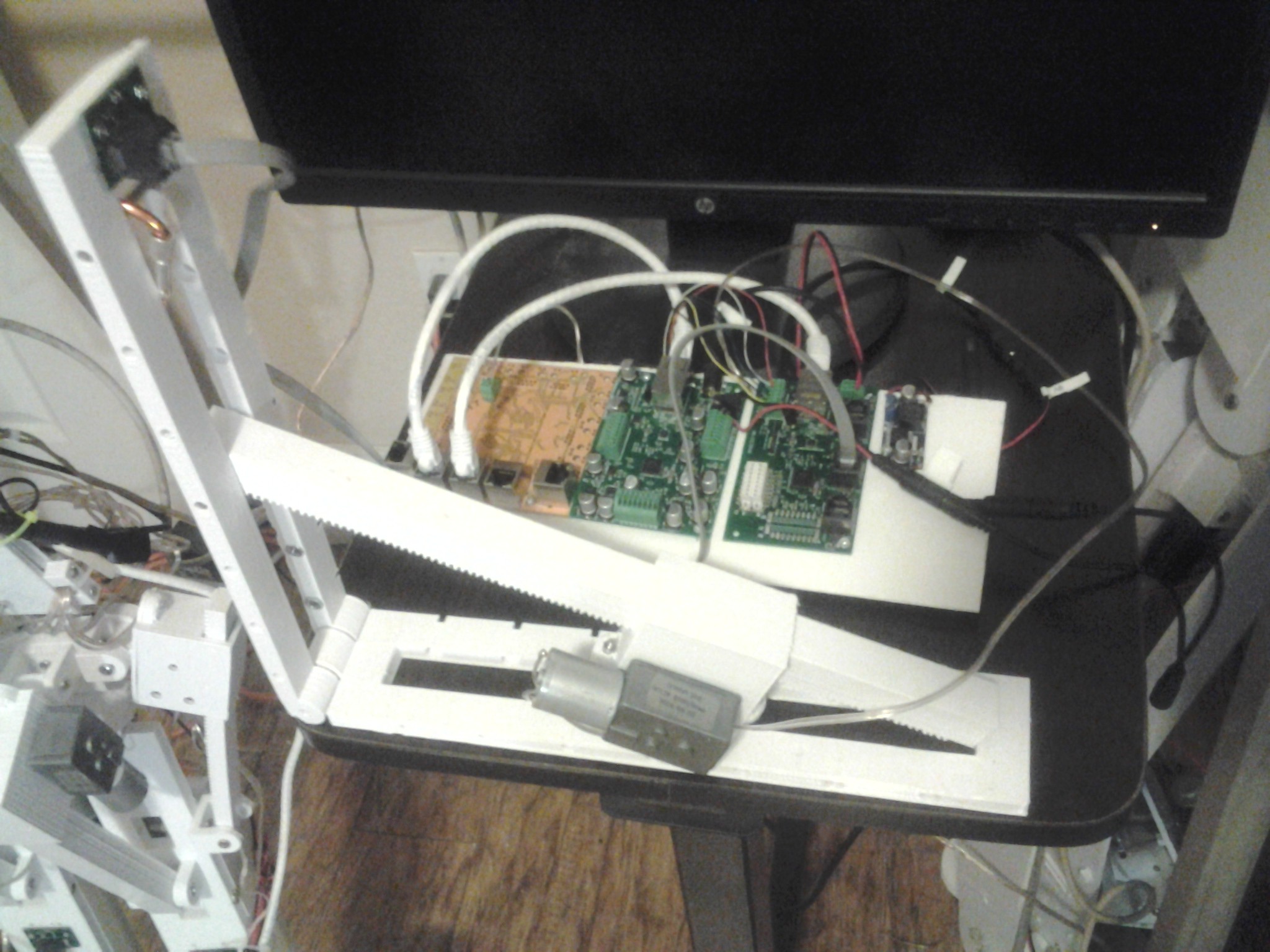
a) Linear Actuator (1) - Rack and pinion design: low cost gear motor connects (using a clamping coupling) to a pinion which moves a connected rack. This design provides a startling amount of holding strength, and acts somewhat like a low cost, light-weight stepper motor because the gear teeth are somewhat far apart.
I think, personally, that this particular product in the Robot Kit is potentially one of the most valuable, perhaps after the 3 PCBs, because I searched and searched for linear actuators, but most of those being sold are metal, heavy, and expensive. For a robot that is going to use 9 linear actuators just for the lower body, that would be very heavy and expensive. This rack and pinion design plastic linear actuator has more than enough strength, is much lighter than a metal actuator, and is about 100x cheaper.
 |  |
b) Linear Actuator (2) - Linear screw design: low cost gear motors connects (using a clamping coupling) to a lead screw/threaded rod which pushes a plastic rod that has an embedded nut. Much slower, but much stronger than the rack and pinion design. This linear actuator could be used on a robot to push a large weight, but is too slow for most robot applications. Nonetheless there is plenty of room for adapting the basic design for a wide variety of applications.
c) Touch Sensor - Conductive foam surrounded by metal tape on each side and enclosed in plastidip. Two wires coming from the sensor can be connected to the ADC ports on the EthAccel to log (up to 100 times/second) the variable resistance of the sensor. Large or small size.
 |  |
 |
3) Test Devices
a) Three-wheel robot - 20mm (w) x 15mm (h) x 20mm (d) robot with 12v battery (note battery: will be smaller lithium ion battery with an optional charger), banana pro, 2 switch-mode voltage regulators, and a small banana pro power adapter PCB (converts regulator 5v to USB and SATA connectors). Robot has two motors connected to clamping couplings that turn plastic wheels, and can be controlled wirelessly (untethered) using a Bluetooth keyboard and/or remote desktop into the Banana Pro.
 |
b) Robot motor testing weight lifting arm - Plastic two-part arm that can be used to test the strength of a motor.
 |
Coolest Parts of this Project:
1) All open source hardware and software. problem robot kit solves- while other people work on robots for themselves, keeping their designs and source codes to themselves, this kit is for other people to be able to build robots too. In addition, this design is low-cost and logical- no exotic hundred dollar pieces of advanced equipment, no new complex untested or proprietary software language- this kit is based on the most basic and only the most necessary, common and popular components.
2) Totally Modular: uses 100Mbit/s ethernet, Cat5 network cable, RJ12 cable a) Users can simple just add as many or few components as they want: For example simply run only a single EthMotors to control 1-12 motors, or just a single EthAccel to control up to 3 accelerometers+gyroscopes and up to 15 touch sensors. But people can also keep adding multiple EthMotors and EthAccels PCBs just by connecting a 3.3V power wire, and an ethernet cable. Of course, any design using more than a single Eth PCB will require a network switch. The EthSwitch PCB is a very low cost, very compact (10x6cm) option.
b) The "brain" of the robot can be any of a wide variety of PCBs. Currently I use an Intel NUC, or a LeMaker Banana Pro, which run Linux RT PREEMPT, but a Raspberry PI, etc. anything that can run Linux can work. Then the most amazing thing is that, how do you connect the brain? Just with a power wire, and a single network cable, that's it. You can connect/disconnect a wide variety of "brains" very quickly and easily.
c) I could have used USB, but that requires a vendor id, while ethernet only requires a MAC address which are free. I2C and SPI cannot be used, because they do not use differential paired wires, and so cannot go over long distances. Low Voltage Differential Signaling (LVDS) could be used, but ethernet is far more common and therefore much less expensive.
d) The EthMotors, EthAccels, EthSwitch PCBs can be moved from one robot to another with very few changes- even entirely different designs- like motor at the joint or motor in a linear actuator "artificial muscle", wheeled and/or legged robot designs are easily assembled.
3) Low Cost- many people want to experiment with robots but not for $100,000! This puts the cost closer to $100. 4) Very easy to problem solve: When something goes wrong with an EthMotors, EthAccels, etc. one only needs to connect the Eth PCB to any network and run the Robot program on a network connected computer. The Robot app will find any and all available Eth PCBs on the same subnet by sending a broadcast DHCP/UDP packet. This helps problem solving, because the EthAccel, for example, can be removed from the robot and brought to a work bench to test it.
4) 3D printed "rack and pinion" design: a) provides tremendous stability b) allows for small light motors to be used c) acts light a stepper motor in that each gear tooth is far enough apart so that "steps" are created when moving the DC gear motor.
5) Motor and gear clamping coupling- how do you connect a motor shaft to a 3D printed part? This is a great question for makers. This design offers a simple and low cost solution. a) Very clever and easy to use clamping coupling design connects 3D printed plastic part to motor shaft, unlike set-screw couplings, with a very tight unmoving coupling. b) There is a trick to the coupling: You must use a large pliars to turn the clamping hex head set screw in the final turn, and the same is true for unscrewing the set screw. in addition, the clamping coupling works best when a smaller set screw is used in one screw hole (on the motor shaft), while a longer screw is used in the second hole- in order to keep the plastic and aluminum coupling linked together.
6) Scripting language includes "TurnMotor" instruction to simply turn a motor with some strength and direction for some duration in milliseconds. In addition a "MotorAccel" instruction links a motor to an accelerometer+gyroscope+magnetometer sensor. This instruction connects a motor to an angle of an accel/gyro/magneto, for example, LEFT_FOOT_MOTOR must hold LEFT_LOWER_LEG_ACCEL (robot body segment) to 0 degrees (vertically). By adding motor-accel associations, complex multi motor scripts can be achieved.
7) Real-time (using PIC32 MCUs and Linux Preempt kernel) recording and logging of accel+gyro+magneto sensor data every 10us, and a 3D window to play back the motions of the robot forward or backward in slow motion using a 3D model of the robot.
8) Robot stands on it's own and is stable standing on one foot.
9) Robot torso with legs and all electronics weighs only 10 pounds
10) Ethernet network design allows a wide variety of architectures. Currently PIC32 (MIPS) is used for EthMotors and EthAccels PCBs, but the code can very easily be ported to ARM or other architectures, because the low level TCPIP drivers are common for most ICs, and the Robot firmware code is written in C.
11) Wide variety of voltages can be used. I am currently using 36V, but 24V, 12V- any voltage over 7v can be used - whatever fits into the DRV8800 motor voltage range will work, although the motor strengths used in any motion scripts would need to be designed around the source voltage (in other words 36v will use a smaller strength thrust than 12v for some robot body segment to reach a particular angle).
Some Robot/Device projects possible with this Robot building kit and development environment:
*two or multiple-leg walking robots (one example: a walking 4-leg table)
*multi-wheel robots
*device that pours two-part plastics into a mold within a vacuum chamber
*flying devices that are tethered to the ground
*upper-body-only robots
*robotic arms, hands and fingers (including touch sensing)
Robot/Devices that are probably not a good fit for this Robot building kit, but for which the internal design details of the open-source Robot development environment could serve as a good starting point:
*drones, compact flying devices (these need to have highly optimized electronics to reduce weight)
Future Enhancements
EthMotors4 - smaller and lower cost EthMotors, controls only 4 motors
EthMotors8 - smaller and lower cost EthMotors, controls only 8 motors
EthMotors_DRV8870 - allows the ability to control stronger motors (up to 3.6A) using the Texas Instruments DRV8870 motor driver IC.
EthMotors_Stepper - allows the ability to control stepper motors over an ethernet cable.
EthMotors, EthAccels that use the Microchip ATSAM4E8C ARM IC as the main microcontroller.
Hackaday Prize information:
1. The challenge the project addresses: Many people want to build robots, but getting into robots can be confusing and very challanging: how do I connect a motor to a 3D printed part? How do I move the motor through software? How can I know what orientation the robot body segments are in? For a beginner, or even an intermediate user of computers and electronics, getting started with robot building can be a steep uphill and frustrating battle.
2. How this project will alleviate or solve the problem that people who want to build robots are quickly overwhelmed by the complexity of the task: The ScienceRobot Robot Building Development Kit addresses all these challanges, and is completely open-source hardware and software so how it works can be completely understood and customized. The simplicity and logic of this design, in addition, to the open-source nature make this a smart choice for a person who wants to start building robots but does not want to have to reinvent the wheel by designing a power system, communication system, motor controller PCB, accelerometer/gyroscope controller, and the accompanying real-time software to turn multiple motors and read thousands of samples a second in real-time. The robot development kit consists of Ethernet Modules/PCBs that are all connected with 3.3V power and an ethernet network cable. These Ethernet (or "Eth" for short) modules are currently based on the PIC32 (but can easily be ported to ARM or other Architectures): 1) EthMotors - controls up to 12 motors (1 amp maximum, although ) 2) EthAccels - connects up to 3 accelerometer+gyroscope+magnetometer sensors via RJ12 cable using I2C to communicate with the PIC32 MCU. 3) EthSwitch - a small compact 8 or 16 port 10/100Mbit/s ethernet switch that connects all the EthPCBs. Any computer running the Robot app can connect to any and all of these Ethernet PCBs simply by connecting a network cable to the EthSwitch. The brains of the Robot app is the scripting language that allows for real-time control over the motors and sensors. For example, you can make a script like this:
1000,TurnMotor(MOTOR_LEFT_FOOT,-5,2000) #at 1000ms turn the Left Foot motor counter-clockwise with thrust=5 for 2000ms
4000,MotorAccel(MOTOR_RIGHT_FOOT,8,1000,ACCEL_RIGHT_LOWER_LEG,X,10,-1,1) #turn the right foot motor with initial thrust=8, with a timeout of 1000ms until the accelerometer on the right lower leg reaches 10 degrees (+/-1 degree) around the X axis (pitch).
So the left foot motor will start turning after 1 second, will turn for 2 seconds, then stop, 1 second later, 4 seconds into the script, the right foot motor will strive to move the right lower leg until it reaches 10 degrees around the x axis. The robot code already knows which direction the motor must turn in to reach the target angle and knows what thrust to use to come to a stop in the target range. In addition, there are numerous instruction flags, like "CONSTANT_THRUST=8" and "MAX_THRUST=10", that allow a user to control various aspects of the motor motion.
While other people work on robots for themselves, keeping their designs and source codes closely guarded secrets, this kit is for other people to be able to build robots too. In addition, this design is low-cost and logical- no exotic hundred dollar pieces of advanced equipment, no new complex untested or proprietary software languages- this kit is based on only the most basic, necessary, common and popular components.
3. I think this Robot Building Kit and Environment have the potential to be world changing because there are analogous world movements that have preceded this Robot kit, for example, the personal computer was initially just built in very small scale, in garages by hobbyists and electrical enthusiasts, but in a few short years has grown to be a planet-wide product. The same is true for the Arduino which brought hobby electronics to the world, and the RepRap project which has allowed 3D printers to proliferate around the world. So the logical prediction is that, a very similar phenomenon is going to happen for robots. So similar to the Arduino and RepRap, many hobbyiest have a strong desire to do electronics, 3D printing, and robot building- but need a basic kit to get started. In my mind, using Ethernet to connect motors and sensors seems like an inevitable conclusion: USB requires an expensive vendor ID, I2C and SPI cannot go long distances, and LVDS is too expensive- but here low cost no vendor id ethernet has been in front of our eyes in plane sight all this time. The modularity of this design is what makes it an attractive member of any "first robot kit". A single EthMotors can be connected to a Banana Pro/Raspberry Pi/Intel NUC, etc. to make a basic robot. The Robot app runs in Linux, MacOS, and Windows. A single EthAccels can be added to give the robot instant ability to read in accelerometer, gyroscope, magnetometer and touch sensor data, all at once, up to 100 samples/second in order to easily have the various robot parts move to particular angles. If I had not created this system, somebody else would have- it is too logical, low-cost, and simple.
Clearly low-cost smart robots will change the world for the better. Thanks to the development of low-cost robots, robots are planting and harvesting crops, cleaning dishes and clothing, delivering packages, stopping violence, etc.. Humans may never have to do manual labor again. Robots will most likely remove the need for humans to do dull, repetitive, mind-numbing tasks.
4. Images illustrating how this project might be used. 1: wheeled robots 2: legged robots 3: robot arm and hand 4: two-part plastic pouring device
5. Link to repositories: see sciencerobot.com/Download
6. Document all open-source licenses and permissions as well as any applicable third party licenses/restrictions:
All software licenses are specified within the source code, my own software and hardware designs and code are covered under the GPL license.