 rolmie
The first thing to think about when talking about precision is what is actually required. Finally the precision of the whole process is limited by nozzle size and the viscosity of molten plastic. The smallest usable nozzles are 200µm, 1/4 (50µm) of this seemed like good choice of what is required in X and Y. The requirements for Z can be derived from minimum layer height. Objects printed better than 100µm layer height are hardly seen. Again using 1/4 gives 25µm precision in Z.
Neither the printed parts nor off the shelf hotends are manufactured precise enough for these requirements, but Slicers as well as printer firmwares have options to compensate for such errors.
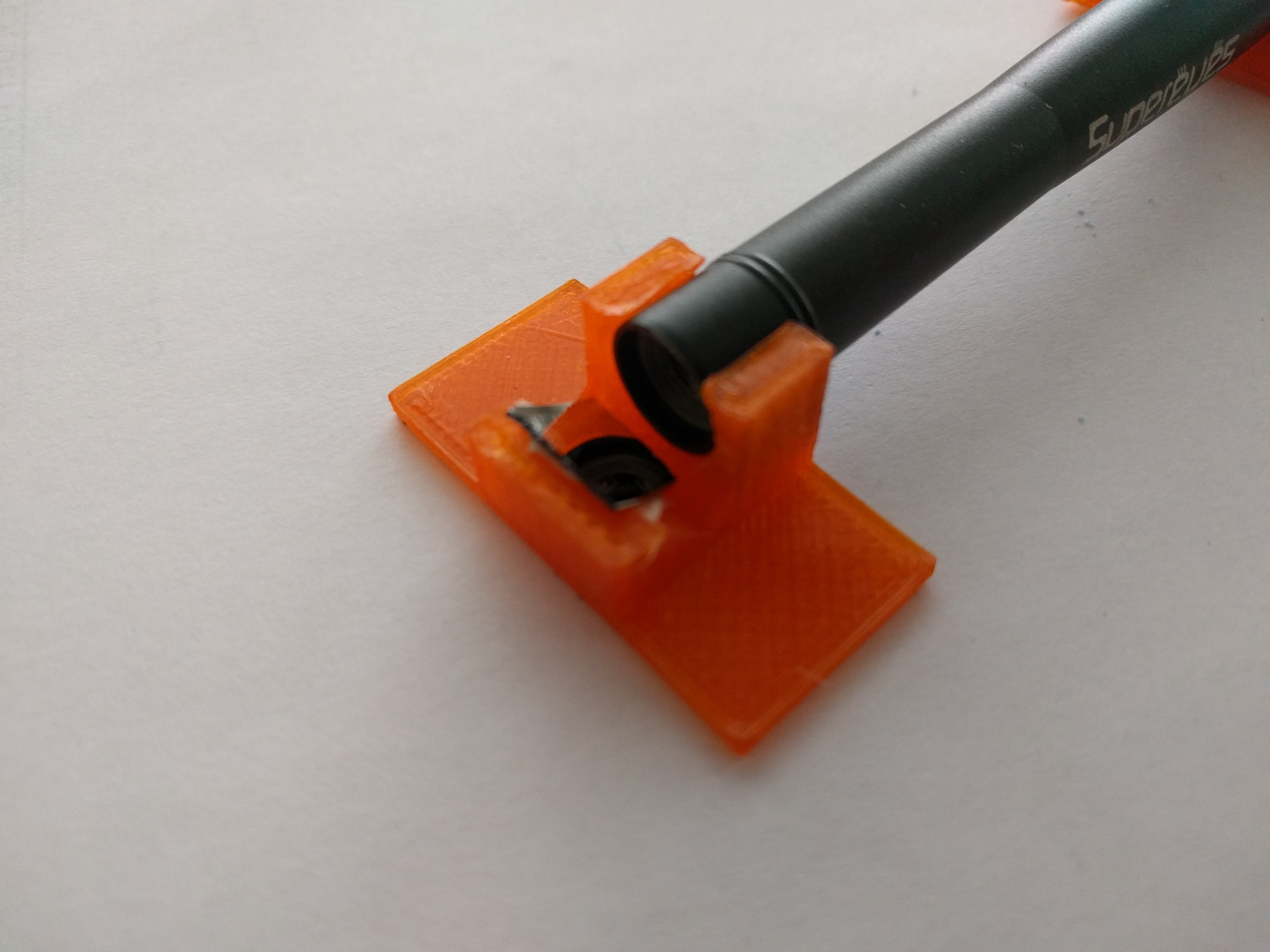
I'm using a low budget USB microscope attached to the build plate to measure the offset of each nozzle. The resolution is in the range of 5µm per pixel, good enough for the requirements.
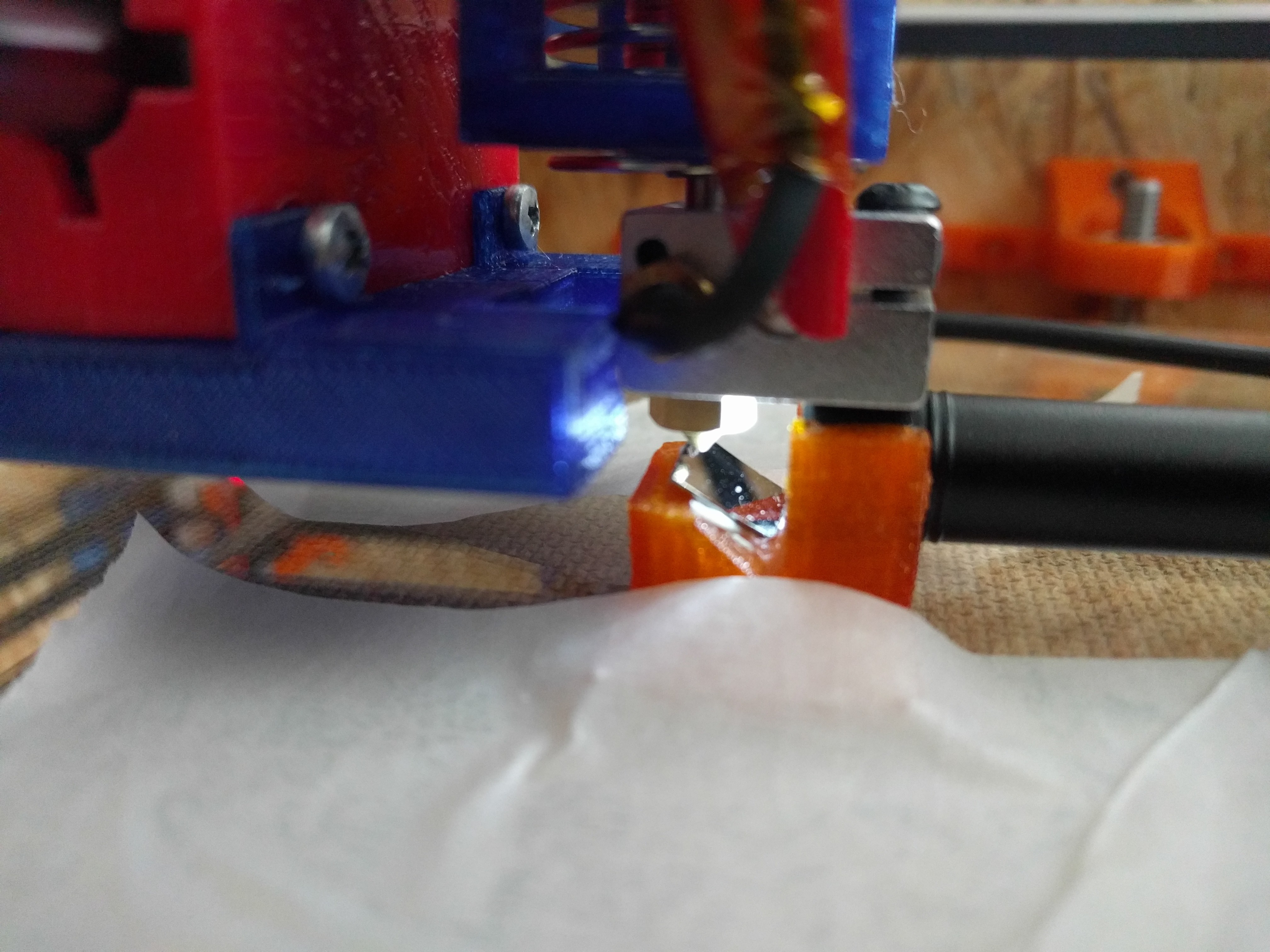
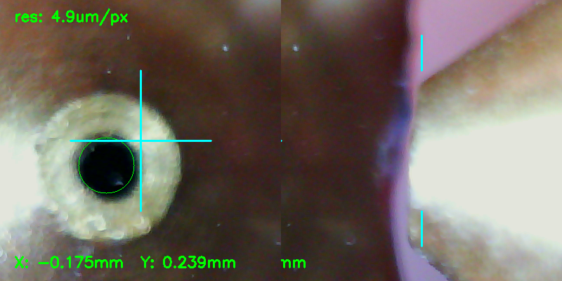
A mirror at an angle of 45° is used to get an upwards pointing field of view in the left half of the image, this allows calibration of XY. The right half of the image has a field of view that allows for Z calibration.
OpenCV and some python scripting are used to extract XY offset and estimate for Z. Instead of relying on camera perspective and resolution, gantry movements and bed height adjustments are used to move the nozzle onto the respective reference points. The calibration is repeatable to about 10-20µm in all three axis.
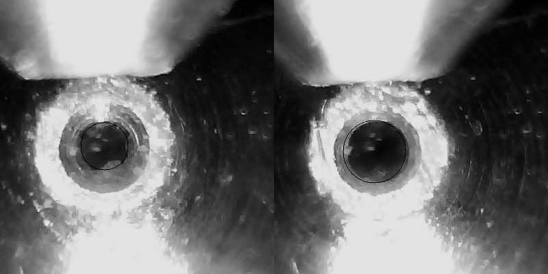
Side by side comparison of two hotends after offset calibration (rotated view).
The process of offset calibration is still a bit tedious, but faster, more reliable and accurate than using thickness gauges and printing variations of vernier scale patters.
Areas for improvement are
- A microscope permanently mounted to the printer, to eg. allow inspection before starting a job.
- Software that closes the loop between loading/unloading tools, measuring offsets, gantry and bed motion
Discussions
Become a Hackaday.io Member
Create an account to leave a comment. Already have an account? Log In.
This is a very cool idea, but I would like to ask how the Z direction is calibrated?
A mirror at an angle of 45° is used to get an upwards pointing field of view in the left half of the image, this allows calibration of XY. The right half of the image has a field of view that allows for Z calibration.
Would like to have a more in-depth understanding of the above text, thank you very much!
Are you sure? yes | no
Very very interesting project to determine the X and Y offset of the second head of an IDEX 3d printer.
I just built an IDEX printer using klipper (https://www.klipper3d.org/) which offers a lot of tools for setting one head, but for independent dual head printers it is difficult to find the offset in x and y except for subsequent iterations with print tests.
This is an open project, is it possible to collaborate?
Are you sure? yes | no
May I ask how you monitored the offset in each direction in your subsequent experiments? I feel that your research direction is very interesting and look forward to your reply!
Are you sure? yes | no
This is a really cool mechanism for validating the offset of a new printhead. I'm curious if the method could be used to calibrate a single printhead. I realize that you need a reference point, but could some other fixed position on the printer serve as that point?
I'm very impressed by this approach. Good work.
Are you sure? yes | no
The only thing that come to my mind would be a kinematic joint for the camera on the Z carriage (outside of the printbed) that allows you to insert the camera with high repeatability, or simple leave it permanently attached.
Out of curiosity, why? Offsets don't matter with a single printhead, Z maybe, but there are better solutions for printbed leveling.
Are you sure? yes | no