 Tindie
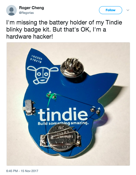
UPDATE: V3 includes an on/off switch!
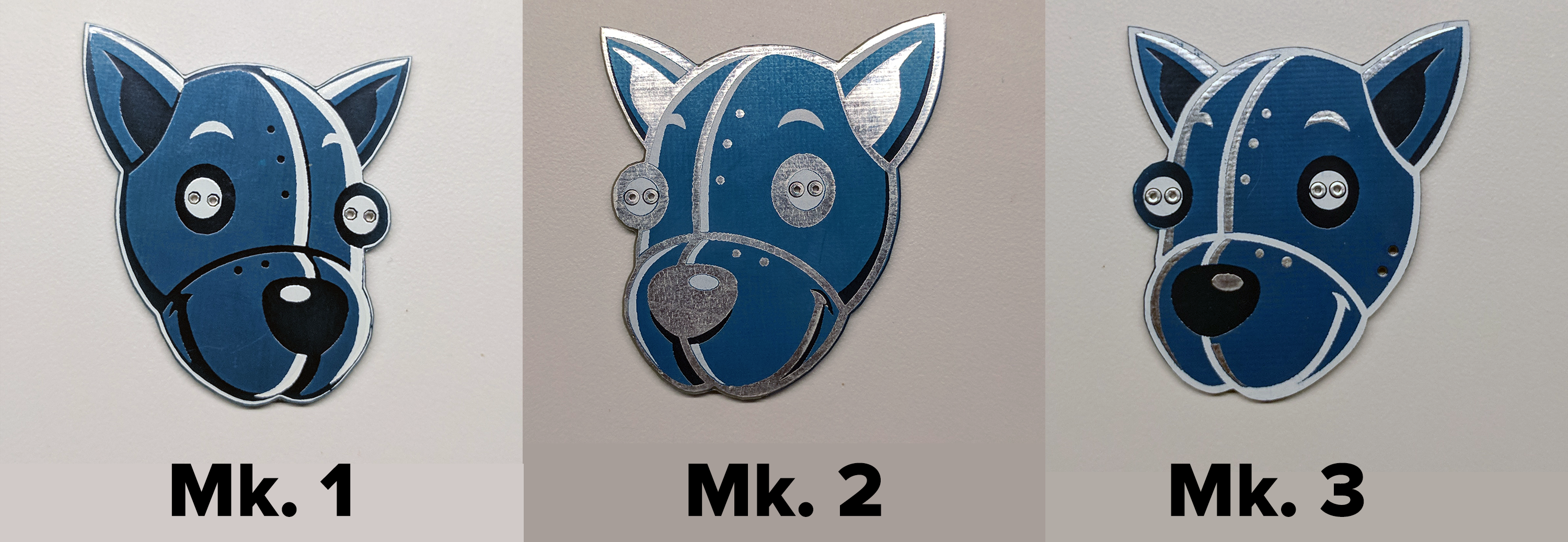
Read Brian Benchoff's post on Hackaday about how this all started when we wanted a badge for DEFCON 25 in under two weeks. Once we got back we realized that it could be made better with a switch and cheaper with BOM cost optimization and the badge iterations.
 Follow
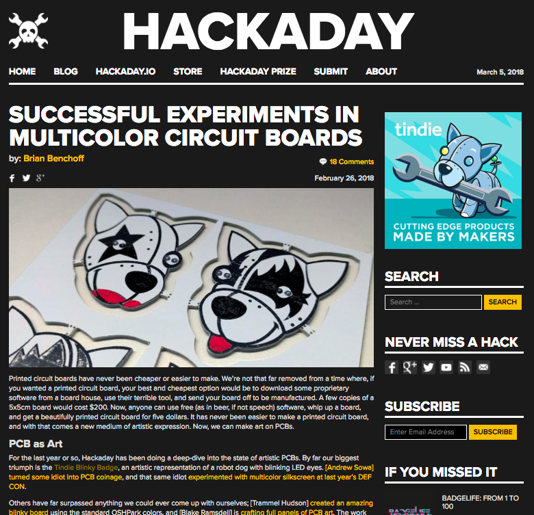


 awkward intelligence
 Benchoff
 Mike Szczys
Can you post the gerbers for just one badge and not the panel?