 endevor100
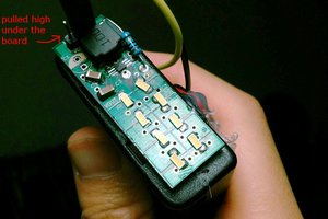
The primary challenge of this project is to wrap your brain around how Charlieplexing works. In my own words, I would say that Charlieplexing uses the tri-state nature of microcontroller (MCU) pins and the one directional nature of LED's to allow for a relatively large array of LEDs to be individually controlled with small number of pins. In concrete terms you can drive n*(n-1) LEDs with n number of pins, so 3 pins drive 6 LEDs, 4 drives 12, 5 drives 20, etc... Wikipedia has a pretty decent explanation (https://en.wikipedia.org/wiki/Charlieplexing) and Maxim Integrated also has a very helpful application note (https://www.maximintegrated.com/en/app-notes/index.mvp/id/1880) to explain the electrical theory, but neither expands very far into the physical placement of the respective LEDs. I know that it takes 9 pins to control 64 LEDs (9 * 8 = 72 LED's max) but how should I wire them? I created something similar to the way the app note drives the 7-segment display were each pair of two neighboring verticals is the common cathode of 8 LEDs and the other 8 available signals are what drives the anode of the particular LED that I want to illuminate. You can see below how I arranged the cathode verticals, for all images in this post the anode is on the left and cathode is on the right. (Note: pin 1 is shown because that's where it goes off to the MCU, but it is never connected to a cathode because I have 8 fewer LED's than my theoretical maximum with this pin count)
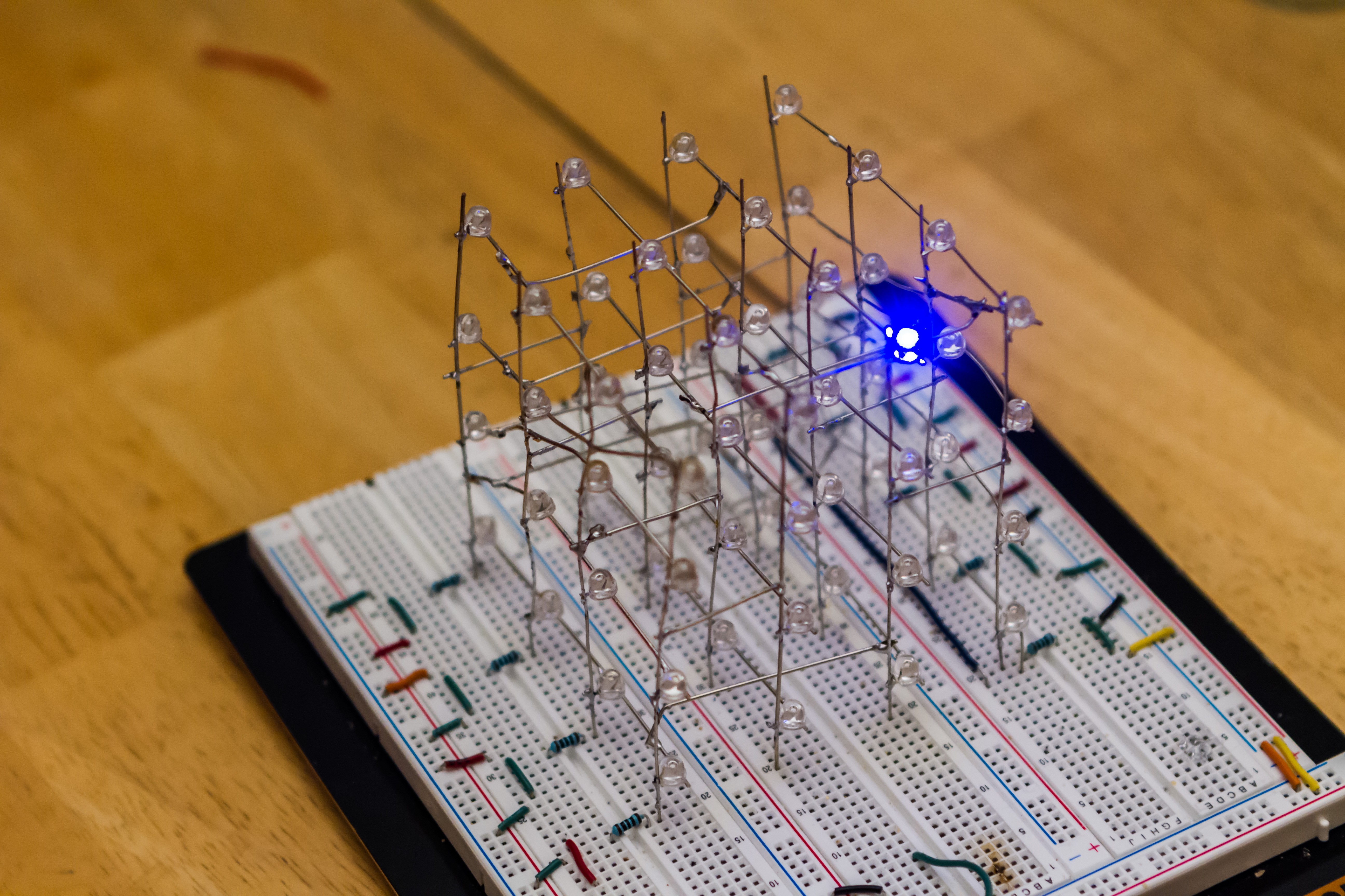
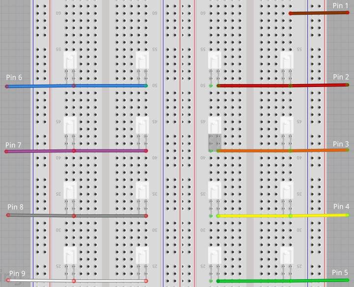 Breadboard wiring of microcontroller pins
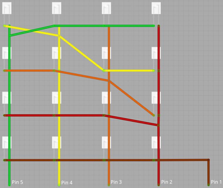
Changing our perspective, if we look at only the first layer of LEDs from the right side of the cube we will see the wiring below. The cathodes of each vertical row are bussed together as described above and there is some creative wire twisting to connect to anodes to their respective pins:
- Pin 1: Comes up off the breadboard and connects to the anode of the entire bottom row
- Pin 2: A line is taken off of the vertical already connected to pin 2 and it is run to the anode of the second LED on the other 3 verticals.
- Pin 3: Starts at the anode of the second LED of the pin 2 vertical, crosses and is connected to the pin 3 vertical, and is then run to the anode of the third LED on the remaining 2 verticals.
- Pin 4: A rotated version of pin 3. Starts at the anode of the third LED of the pin 2 vertical, continues to the anode of the third LED of the pin 3 vertical, crosses and is connected to the pin 4 vertical, and is then run to the anode of the top LED on the pin 5 vertical.
- Pin 5: A rotated version of pin 2. Comes from the pin 5 vertical and is run to the anode of the top LED on the other 3 verticals.
The wires for pin 4 and 5 cross on the top left but can easily be bent out of each others way or the pin 5 vertical can be extended past the top LED to avoid crossing all together.
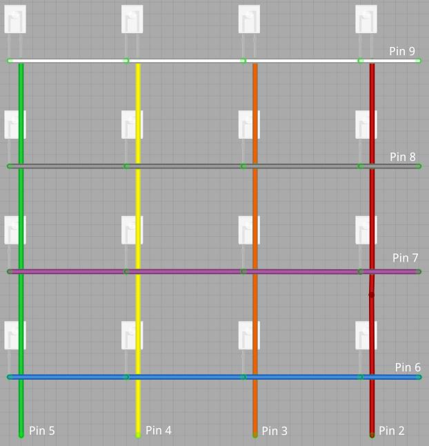
 Right most layer of the LED cube
The next layer of LEDs is much easier to wire. The verticals are the same as the previous layer and pins 6-9 are connected to all of the anodes on a single row starting from the bottom going to the top.
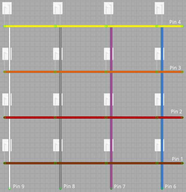
 Right middle layer of the LED cube
The next layer of LEDs in, still looking from the right side, is very similar to the previous one. The verticals are now pins 6-9 going from right to left and pins 1-4 are connected to all of the anodes on a single row starting from the bottom going to the top.
 Left middle layer of the LED cube
The last layer of LEDs, still looking from the right, unsurprisingly looks a whole lot like the first layer. The cathodes are the same as the previous layer and again some creative wire twisting is required:
- Pin 5: Connects to the anode of the entire bottom row
- Pin 6: Comes off the pin 6 vertical and it is run to the anode of the second LED on the other 3 verticals.
- Pin 7: Starts at the anode of the second LED of the pin 6 vertical, crosses and is connected to the pin 7 vertical, and is then run to the anode of the third LED on the remaining 2 verticals.
- Pin 8: A rotated version of pin...
 Failed tri-state attempt #1
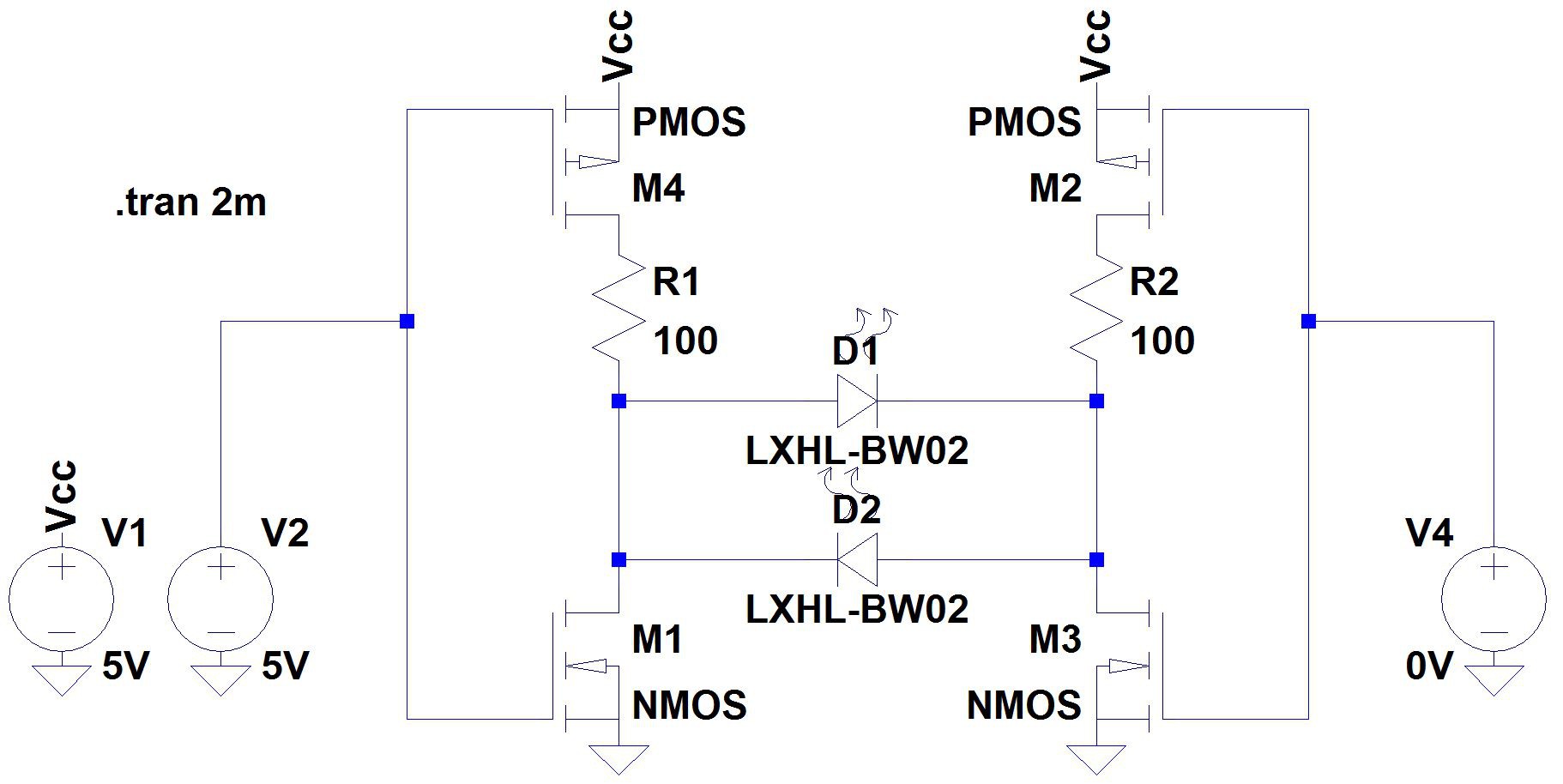 Failed attempt #2, this time with MOSFETs
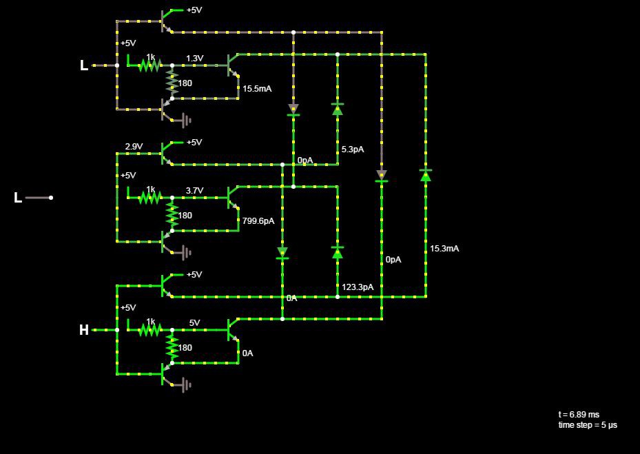
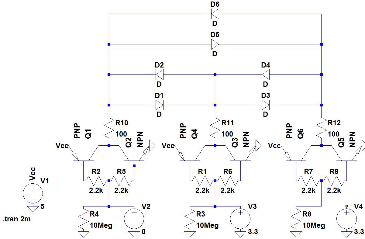 Failed attempt #3, back to BJTs
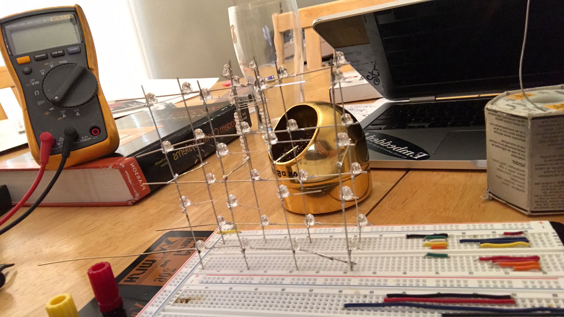

 drojf
drojf
 Stefan-Xp
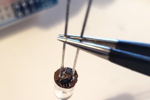
 Sam Ettinger