 endevor100
I had to take a break from writing code for the cube to spend the time on other things, but that didn't stop me from coming up with some very important optimizations. The biggest of them being to use pointers to iterate through the cube array instead of loops. I never really thought loops would work well, but they were a shortcut to getting the cube to light up in the first place. In the previous video I had to turn the room's lights off and have multiple LEDs on at once to achieve a respectable looking intensity. In this video I had the lights on, during the daytime, with the camera's flash on to overexpose things a bit. They're much brighter now.
The reason for this huge jump in brightness is that I am no longer paying the "for loop tax". Previously when I programmed the LEDs to be at full intensity I got at best 1/4th duty cycle from them. Because the LEDs are illuminated individually this meant that the best possible case was each LED being on for 1/256th of the time. Honestly I suppose it's impressive that the LEDs are efficient enough to even be visible at that kind of duty cycle. Because of this short duty cycle I also ran up against issues with parasitics. The pulses were so short that when I tried to light up the whole cube at around 60 frames per second I couldn't get the full voltage (and as a result current) across the LED no matter how small of a current limiting resistor I used. This compounded my issues with dimness.
With my new pointer and ISR based animations I not only save all of the program cycles from the loop computation, but I can use the ISR routine to skip pixels that should be off. This gives me a duty cycle for each LED that is much closer to 100%.
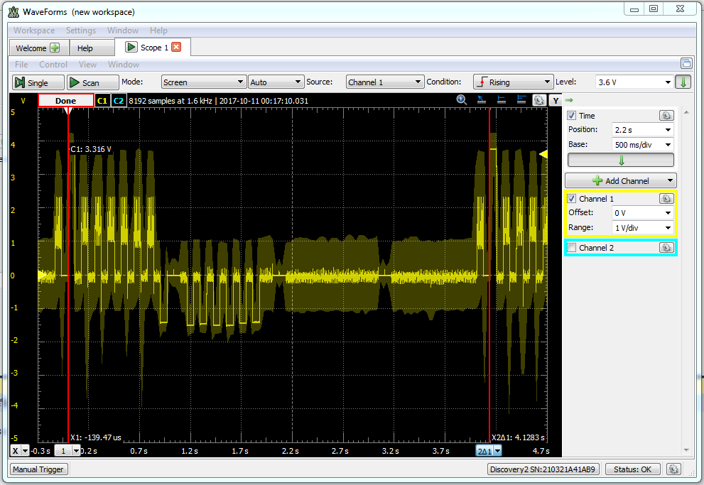
I wish I had taken more oscilloscope captures in my testing process, but hopefully I can explain with the one I did take. Below is a capture of the voltage across a single LED for the whole cube's 4.1s period. Hidden by the label for the cursor on the left is the ~60ms pulse at 3.7V to turn that LED on. It is mirrored again at the right hand cursor because it's the beginning of the next period. That pulse is nice and flat as are the 7 times that pin gets pulled low between ~1s and ~2s so the LEDs are receiving a nice consistent pulse when they're supposed to be on. Vdd is 5V and their are two 47Ω current limiting resistors for each LED so my current through each LED is around 1.3V/94Ω = 13.8mA which I am happy with. The noise on the waveform for the rest of the pulses is understandable because both pins that LED is connected to are floating, but it's not lighting up which is the important part. If you break the waveform up into 64 x ~60ms pulses current is flowing for something like 3.9s of the 4.1s period for something close to 95% duty cycle. I think it's even closer to 100%, but that's about as accurate an observation as I can make from this zoomed out scope capture.
I'm tempted to over drive the LEDs a bit to increase brightness even further, but then I would need to add capacitors to protect from a latched pin. To do that I would need to spend a lot of time prototyping that, and I'm not sure I'll have that anytime soon. Theoretically, a minimum of 30fps*64 pixels = 1920 pixel/second. This would mean that the longest I would want an LED to be on is 1/1920 = .5ms. A capacitor charges 50% after .7 time constants so if I designed for a time constant of 1ms I would have close to full power across the LED for most of the whole .5ms max time I want it on, but would have basically no current flow after 2.2 time constants or 2.2ms if an LED got latched on. Looking at available parts 2x15Ω would result in something like a starting current of 1.3V/30Ω = 43mA (not technically correct, but a very basic first guess) that would slope off rapidly preventing damage to the LED. The 30Ω series resistance in line with a series capacitance of 34uF (2 x 68uF caps) would give a time constant of 1.02ms. That would be my starting point at least, but I would need to extensively test other LEDs from the batch I made the cube with before changing the cube to this system as Charlieplexed arrays are notorious for being hard to troubleshoot because of the various paths for current to flow.
Next up is continued code optimisation, and hopefully at least 4-bit PWM dimming for each LED. I will upload my current code now because it's almost good enough that I'm not embarrassed of it.
Discussions
Become a Hackaday.io Member
Create an account to leave a comment. Already have an account? Log In.