 Yann Guidon / YGDES
As mentioned before, the module is not complicated at all :
- A decoder translates the binary code into a 1-out-of-16 bus
- A diode matrix translates the 16 wires into a 7-wires bus with arbitrary combinations.
- A Numitron displays the state of these 7 wires.
The display and diode matrix are not rocket science anymore. The last log shows the chosen Д9Б diodes use Germanium and we can measure the voltage drop: one segment in series with a conducting diode, all under 3V, draws about 17mA and gives a diode drop of approx. 0.5V (+/-10%) so the segment runs at about 2.5V. Current draw is about 140mA when all 8 segments are on. Luminosity is a bit better at 3.3V.
This means that the module's supply would be in the 3V-3.3V range. This is pretty convenient :-)
However, driving these diodes is a different story. I will refer you to the log 18. Instruction display panel where I explore some demultipexing strategies with relays. The big difference between individual diodes and the Numitron is the common pin for all the filaments... so it is not possible to use the X-Y method...
This means that a 1-to-16 demux will use 15 relays, not counting the 3 buffers, which is out of proportion !
However it is possible to use another method that reverses the current flow with one relay. One 1-to-8 demux is then needed (7 relays), plus 2 buffers and the inverter : 10 relays is more reasonable.
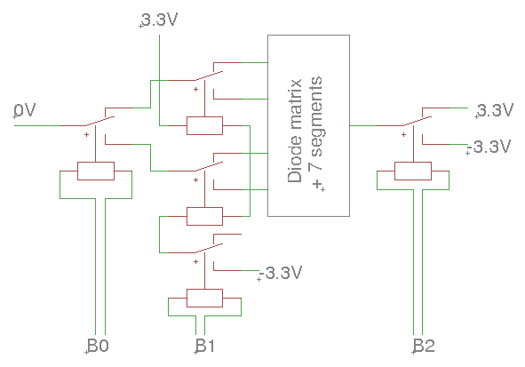
An octal decoder uses even fewer relays and half of the diodes so we can start with this case : One polarity selector, then a 1-to-4 demux contains 1+2 relays.
The polarity selector and the root MUX of the tree use one relay each, that can be directly driven by the input signal. However the 2 branches of the tree need special care. That's the "not so obvious part"...
- Put the two coils in parallel to preserve the signal voltage : this is simple and the signal voltage is preserved but the impedance is halved and this could lead to further troubles in the driving circuit.
- Put the coils in series to preserve the driving current and the voltage is doubled, which is another problem. One solution is to add series resistors to the single coils but this wastes even more energy and the voltage increase might create other kinds of problems for the driving circuit. One alternative to the resistors is to add a second relay to the polarity switch that would allow the module to work with only 3V. This adds one precious and energy-hungry relay...
- The safer solution is to add one relay as amplifier. It might work in CCPBRL mode, which requires an additional 100µF capacitor... It would be kinder on the power supply rails than hard switching and all the bounces. So it's 5 relays and one capacitor.
Here is one option with a buffer relay:
The hexadecimal case is almost exactly like the octal case, but there is a MUX8 instead of a MUX4, with the additional 4 relays. A buffer relay is required to adjust the input impedance... We now use 5+5=10 relays !
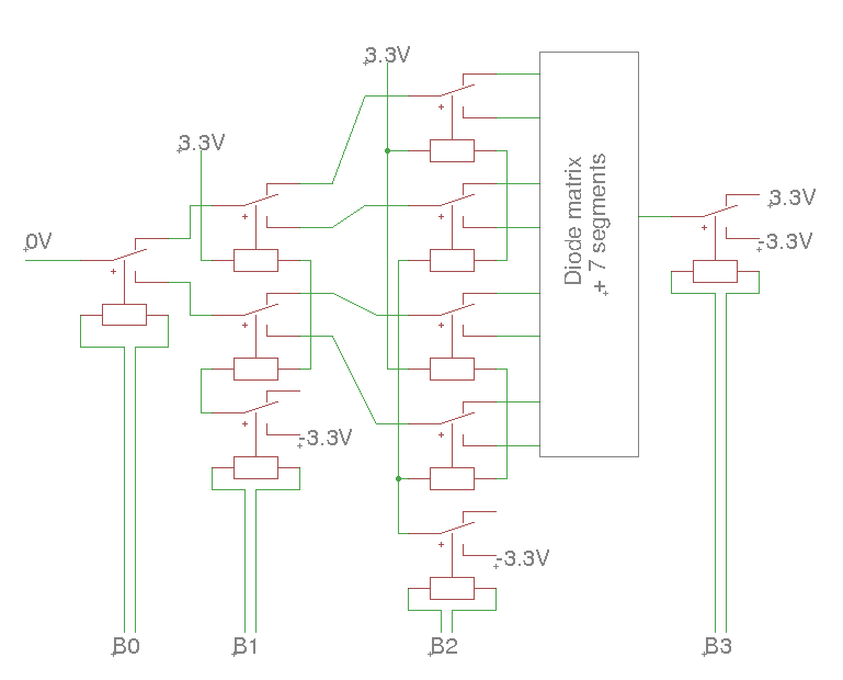
There is however a little "enhancement" to do here :-)
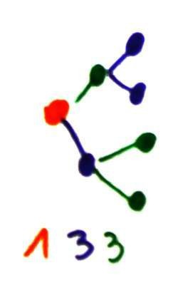
The RES15 start to conduct at about 2V so 2.2V should do, right ? 2.2V×3=6.6V, which is exactly the voltage between the + and - supply rails. So we can switch 3 coils with one relay. Borrowing from previous research (10. More balanced trees !), a little reorganisation gives use the new diagram...
With this method, the driver circuits are better balanced !
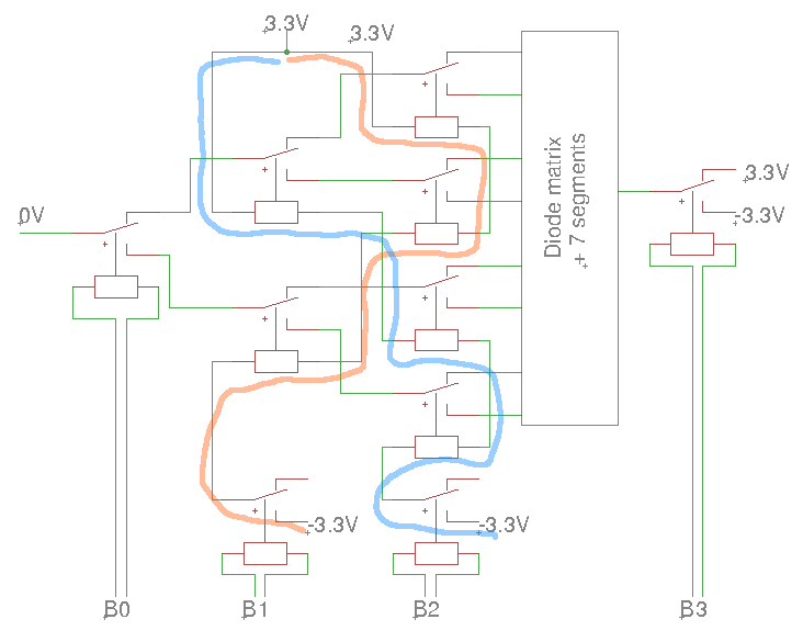
However the circuit is missing some protection against spikes across the coils. Diodes and capacitors would be required... CCPBRL woud be a solution.
20170730:
I tested the relays and made sure they switch under 2V, so 2.2V is good. Here is the "interface" for the binary input, along with the 4 "front-facing" relays.
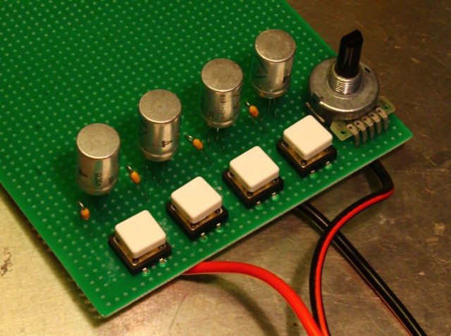
6 more relays to go !
The decoder works !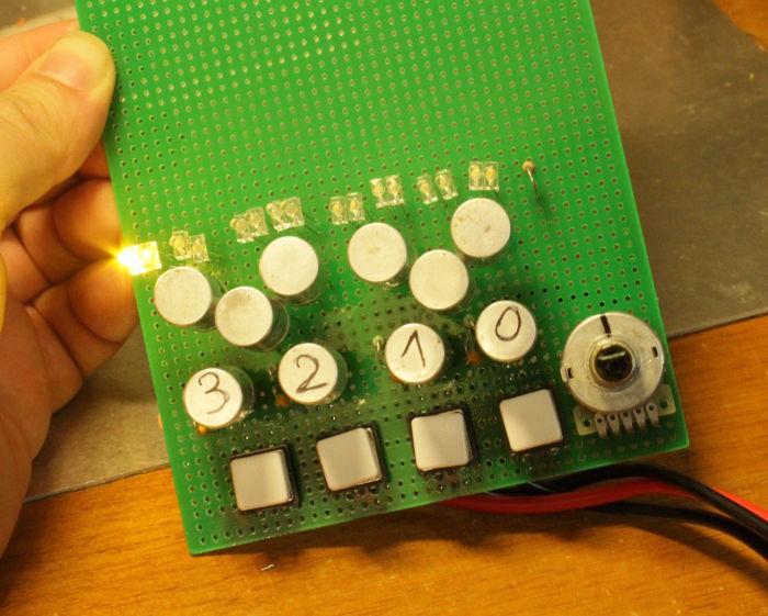
Getting the address bits right was not difficult, I had to swap a few wires. But the video shows the rotary selector functioning with the LED lighting in the correct order.
Power draw:
- Code = 0 => 0A (except for the LED)
- Code = F => -0.37A, +0.12A
The buttons draw quite some current from the negative rail...
Discussions
Become a Hackaday.io Member
Create an account to leave a comment. Already have an account? Log In.