Nelson Phillips
This project is a documentation of significant redesign and considerable development of the Soft Handy V1. It address a number of issues that this design had with its fabrication and mechanical functionality. The principles of actuation are consistent as are the methods of fabrication. It will still use a pneumatically inflated silicone actuator covered with a 3D printed exoskeleton for mechanical consistency. The control system will use already developed components, https://hackaday.io/project/108157-pneumatic-tech-for-prototyping, that will be package into a custom module.
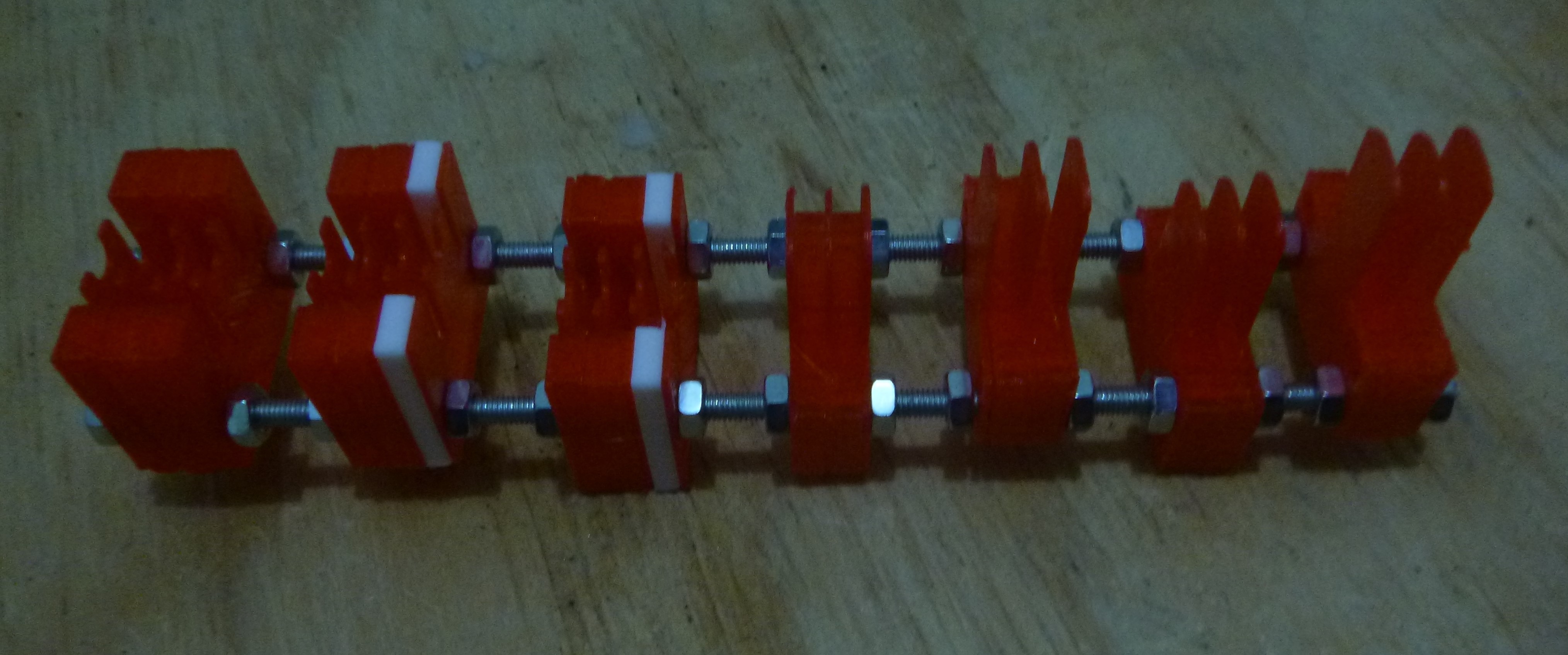
A major extension for this project from other soft robotic systems is that it is able to develop a modular system for this space. This modular system is proposed to make it possible to develop soft robotics more easily and more important give greater flexibility to their design. It does this by deconstructing the actuators molds into the four definitive components that can allow for swapping of size and shape. This way a complex appendage for a robotic hand can be constructed by combining components rather than designing and integrating individually complex parts.

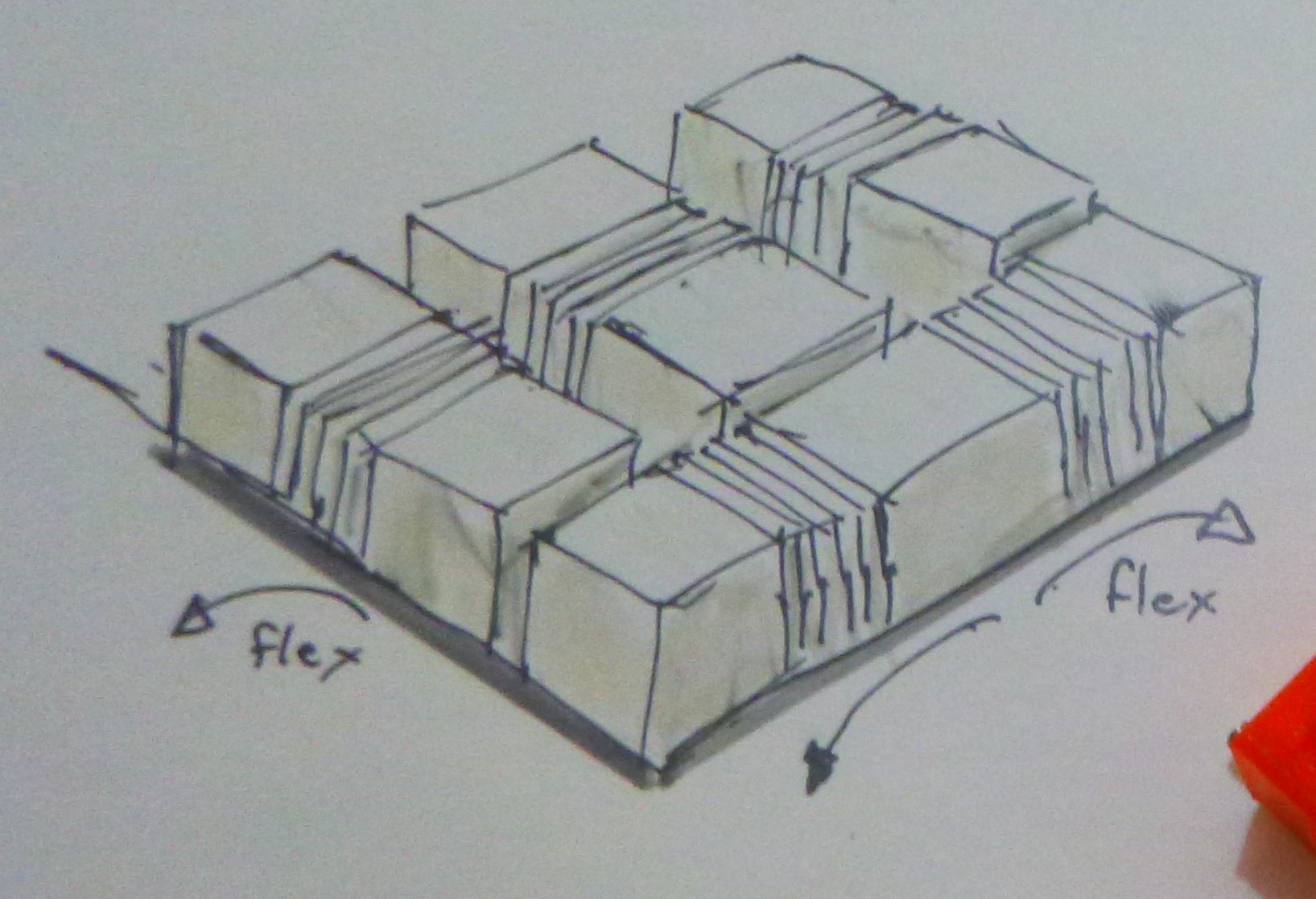
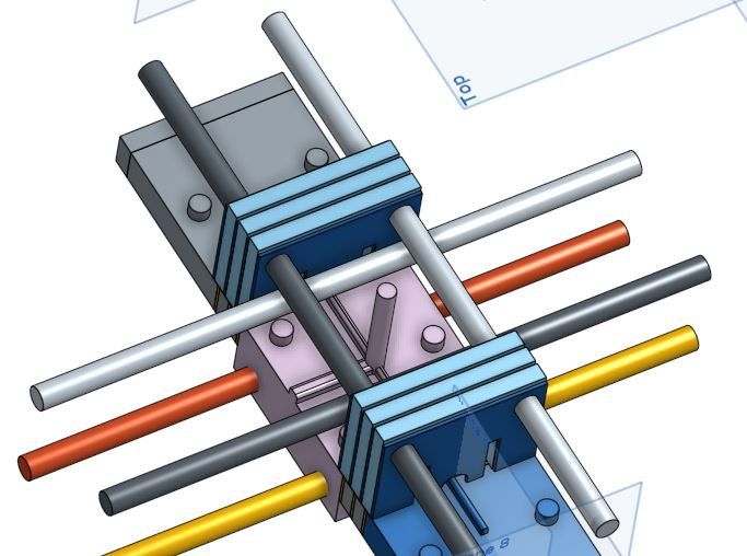
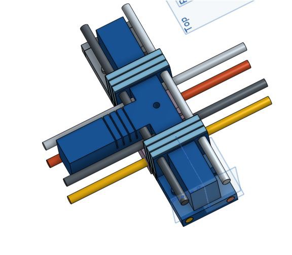
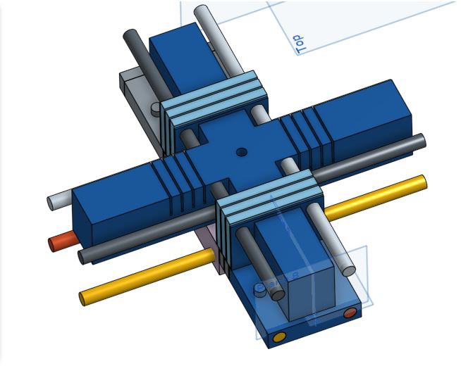
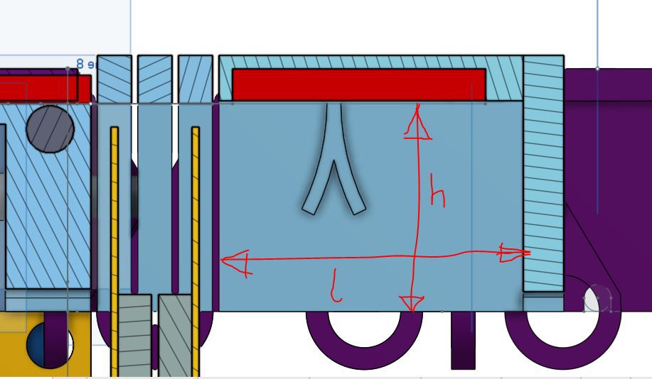
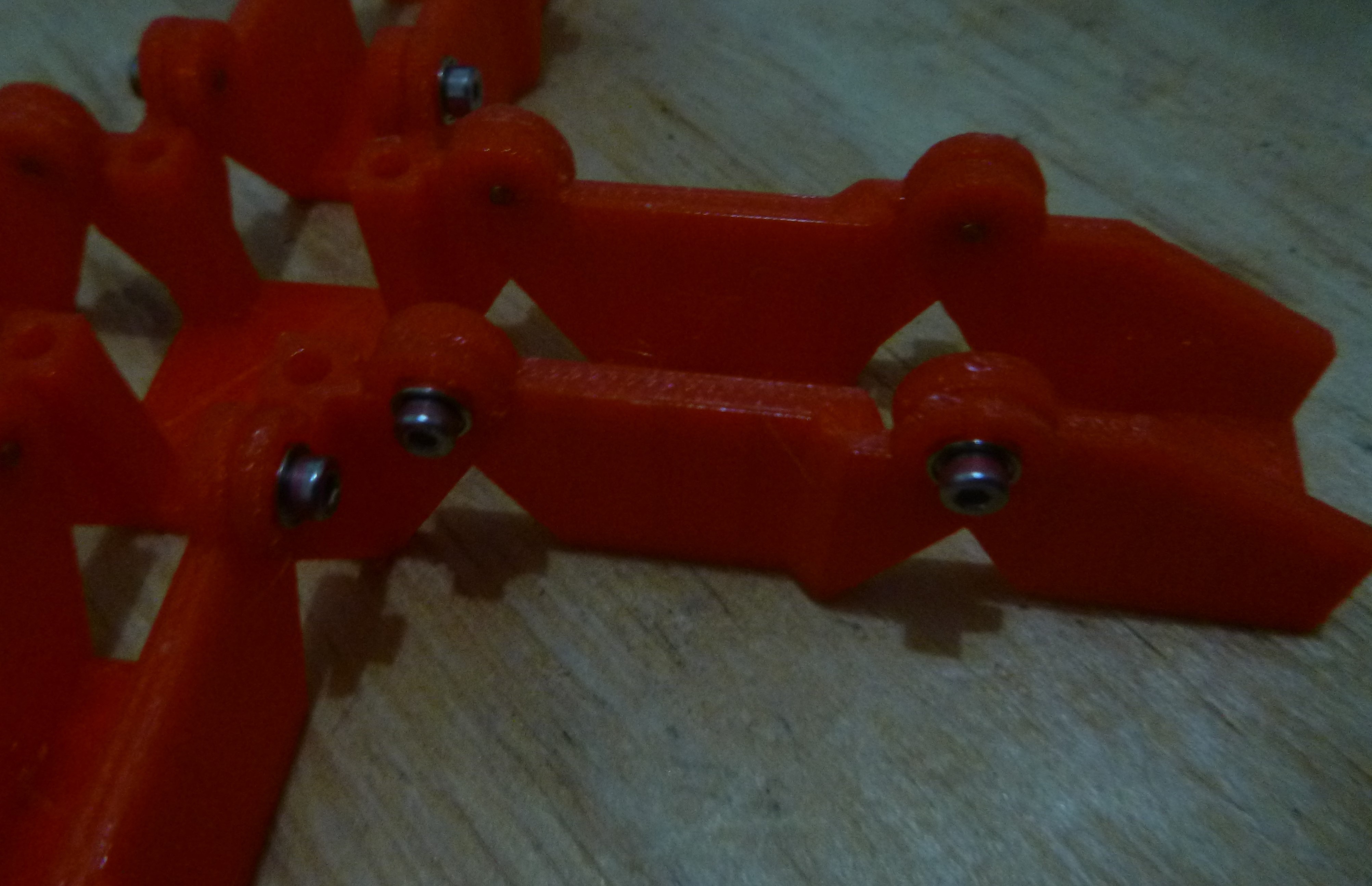
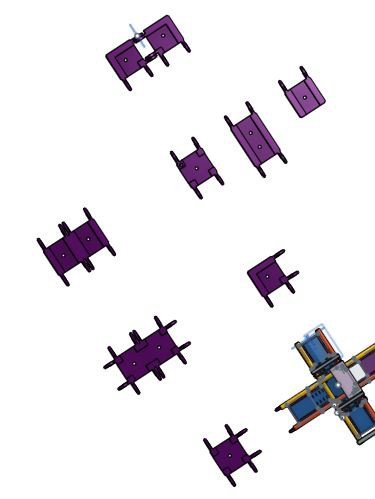
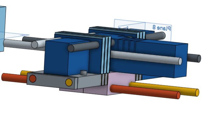
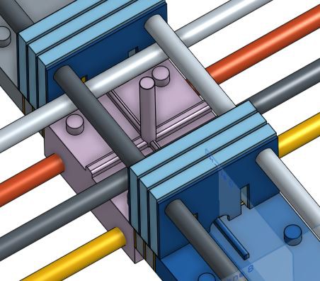
An example of this is the sketch below of how combining a number of sections could make a gripper flex in multiple planes.
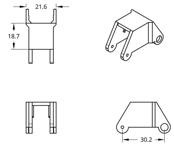
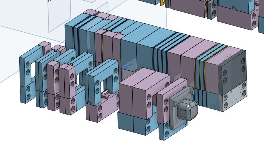
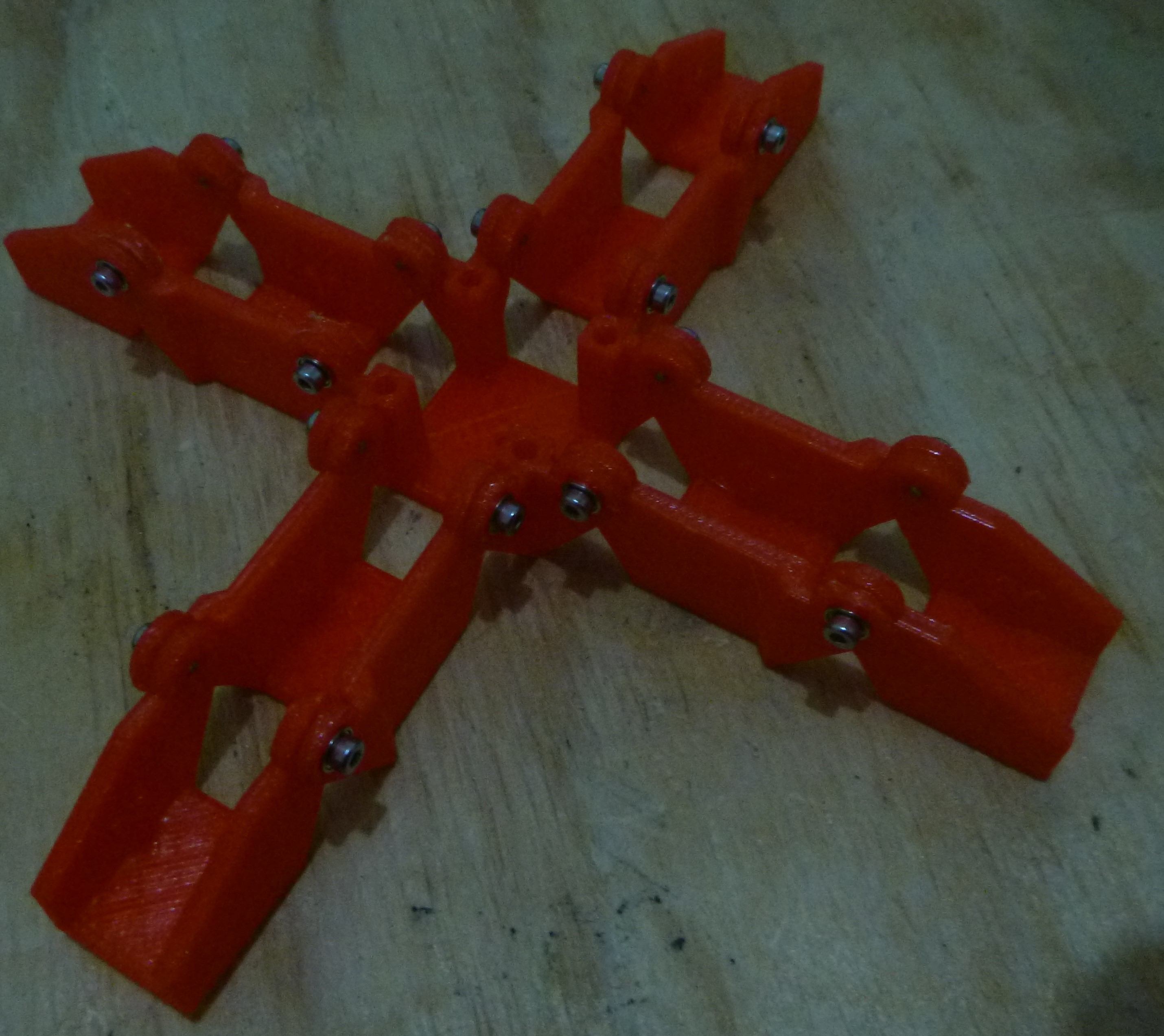
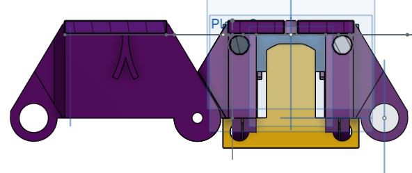
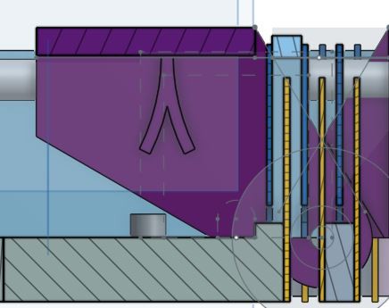
A CAD model of a multiple plane exoskeleton.

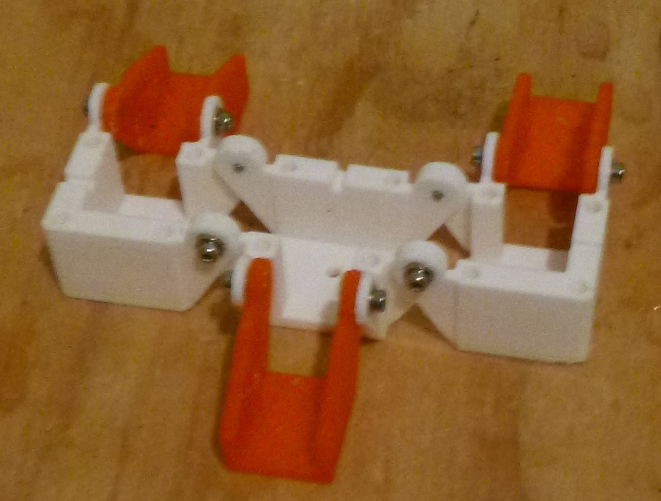
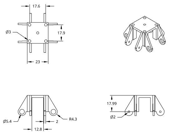
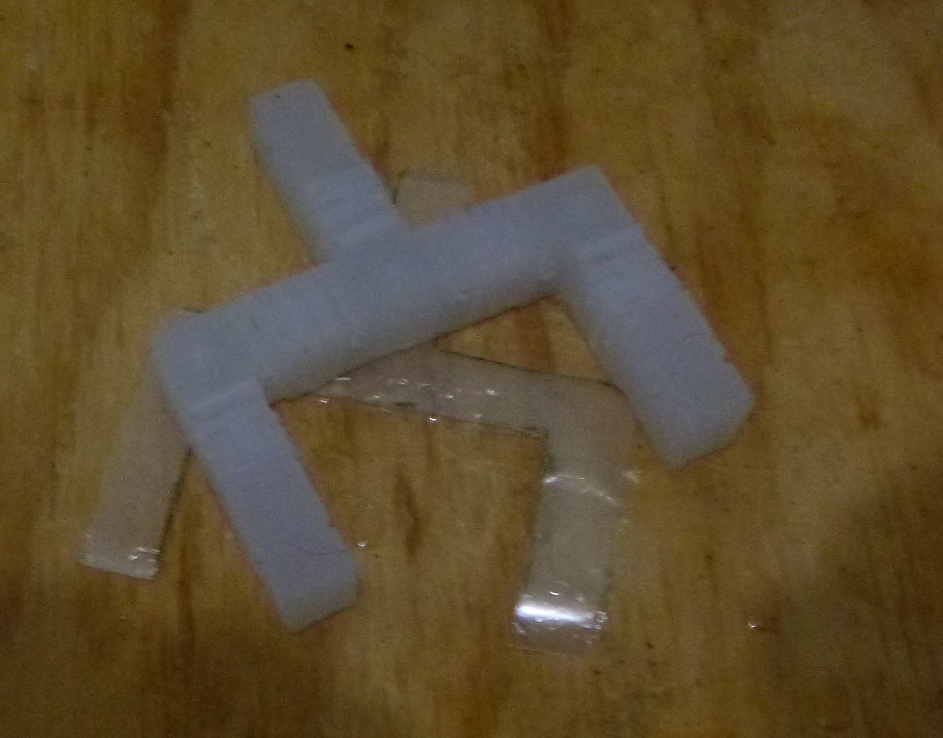
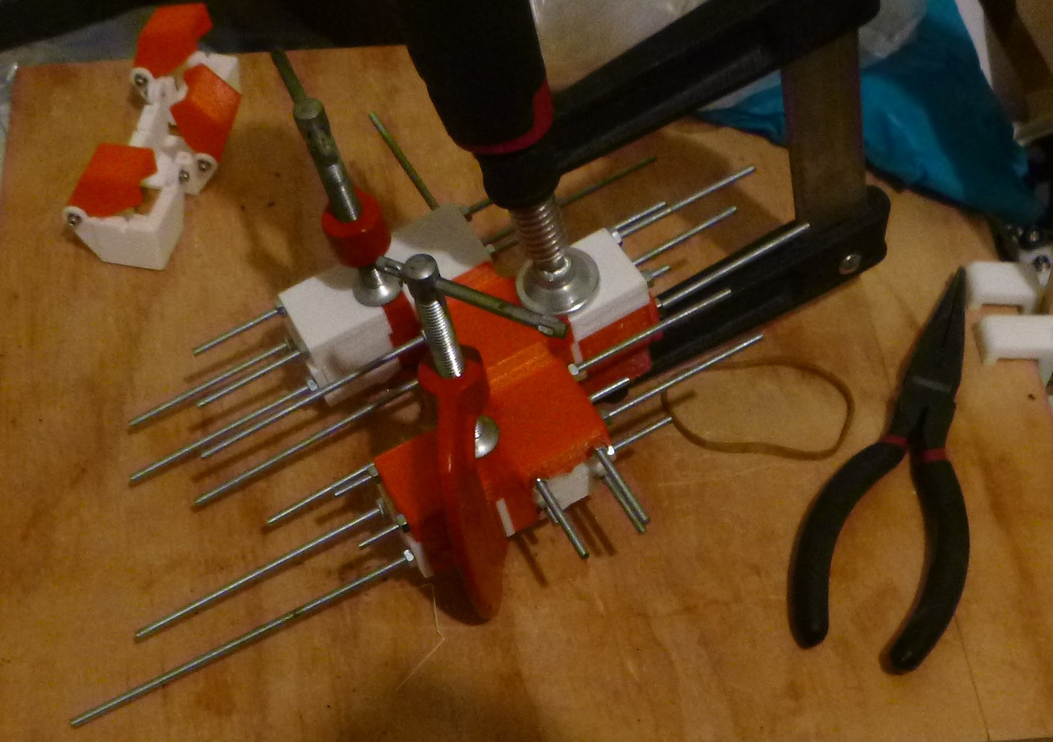
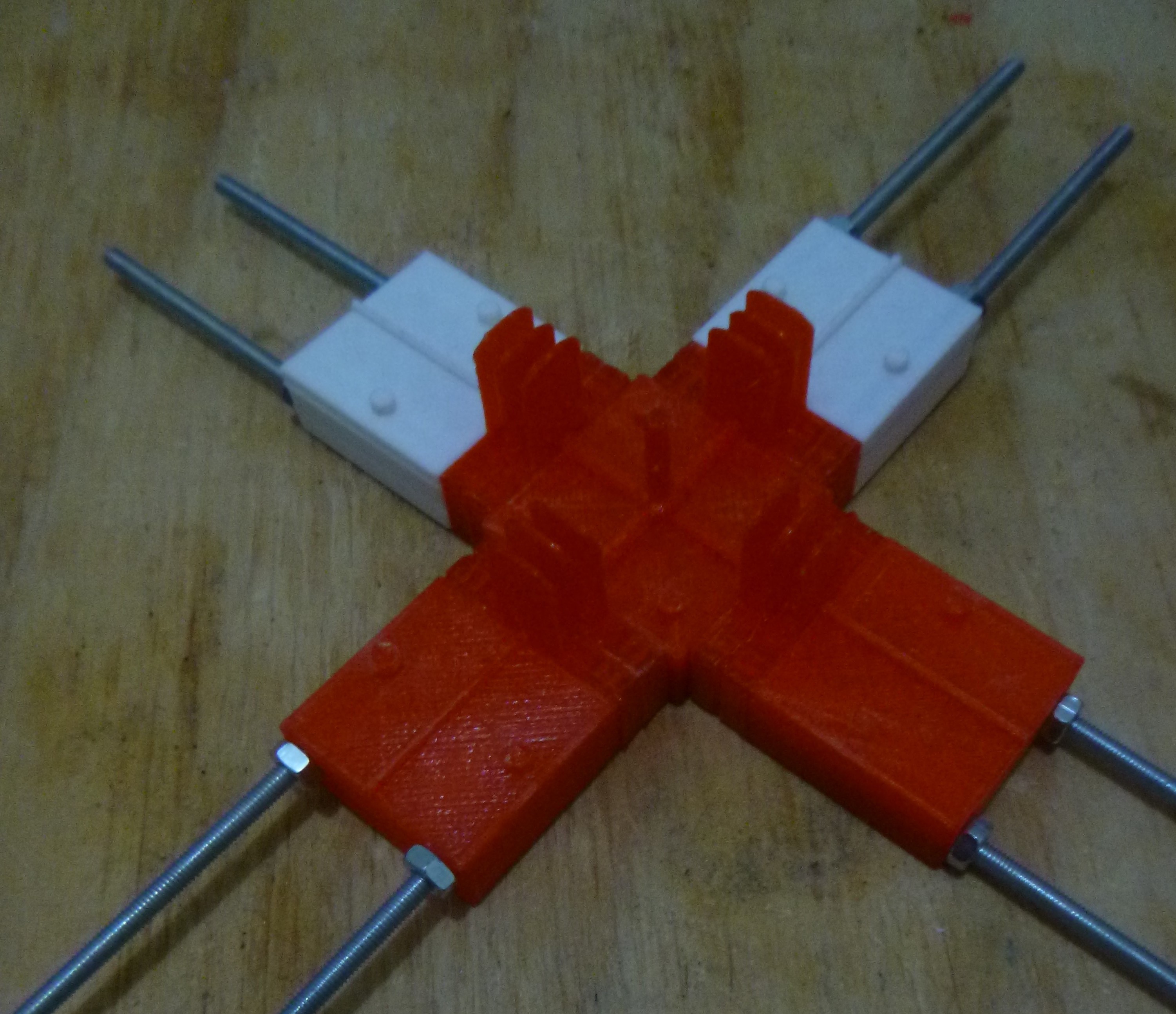
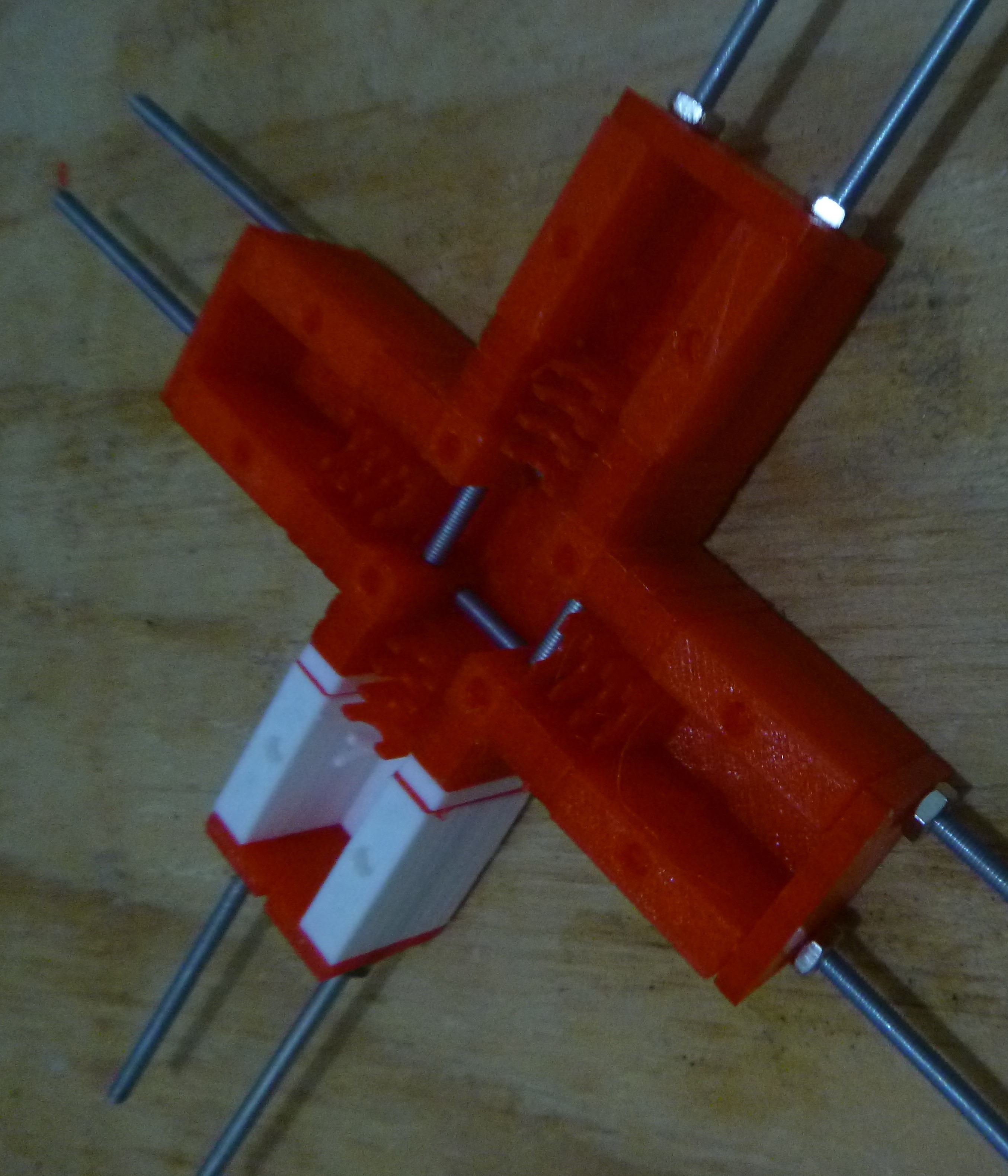
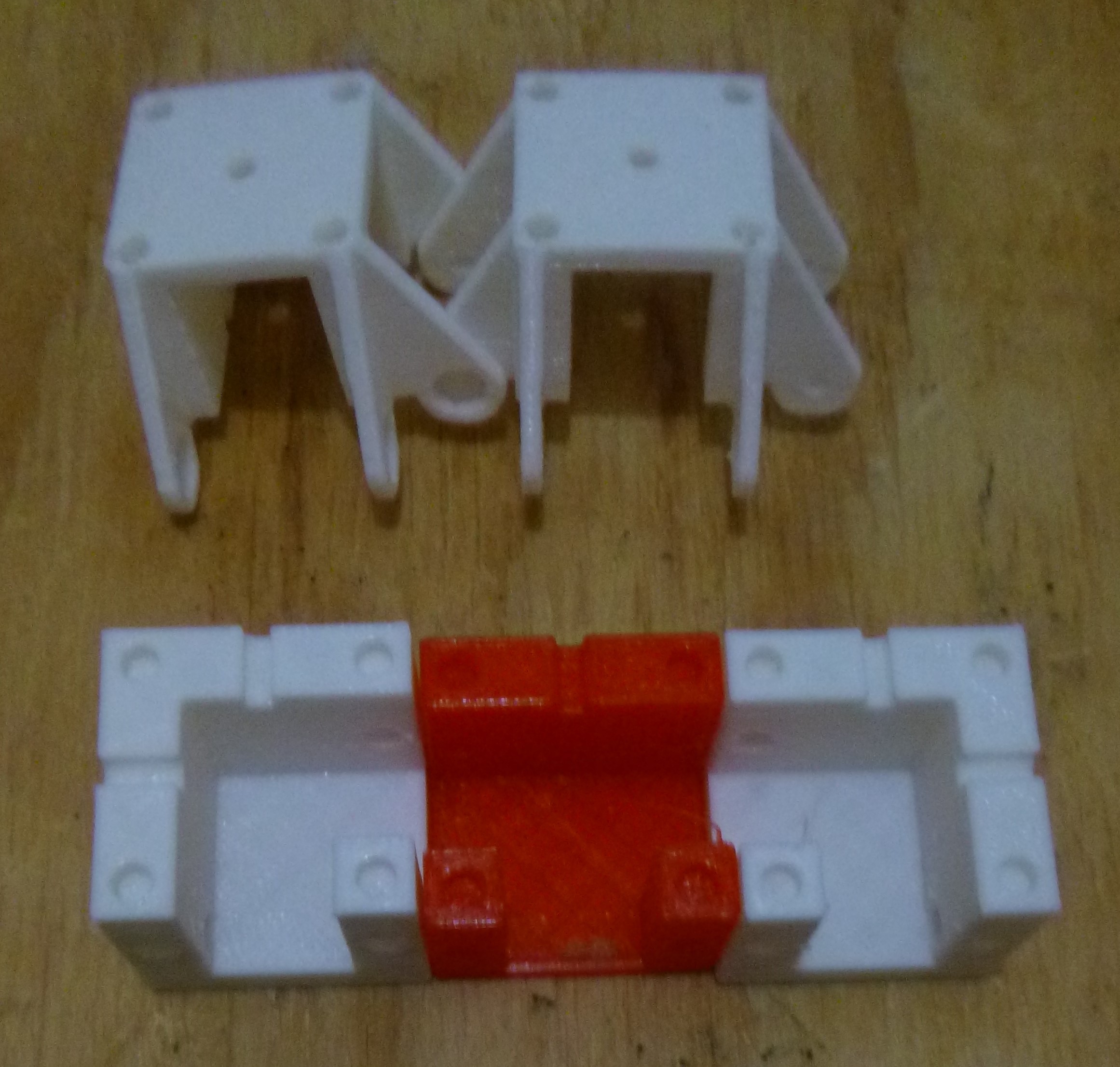
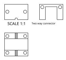
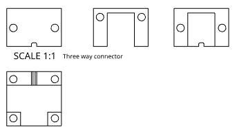
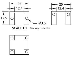
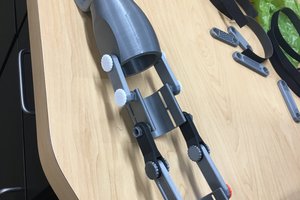
This would be made of join or combining multiple sections together made up from molds like this. Through each component of the molds is a 3mm hole for threaded rods to tie them together.
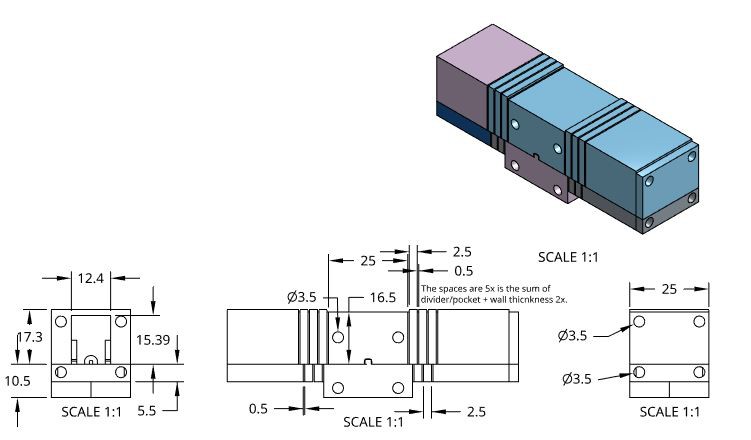
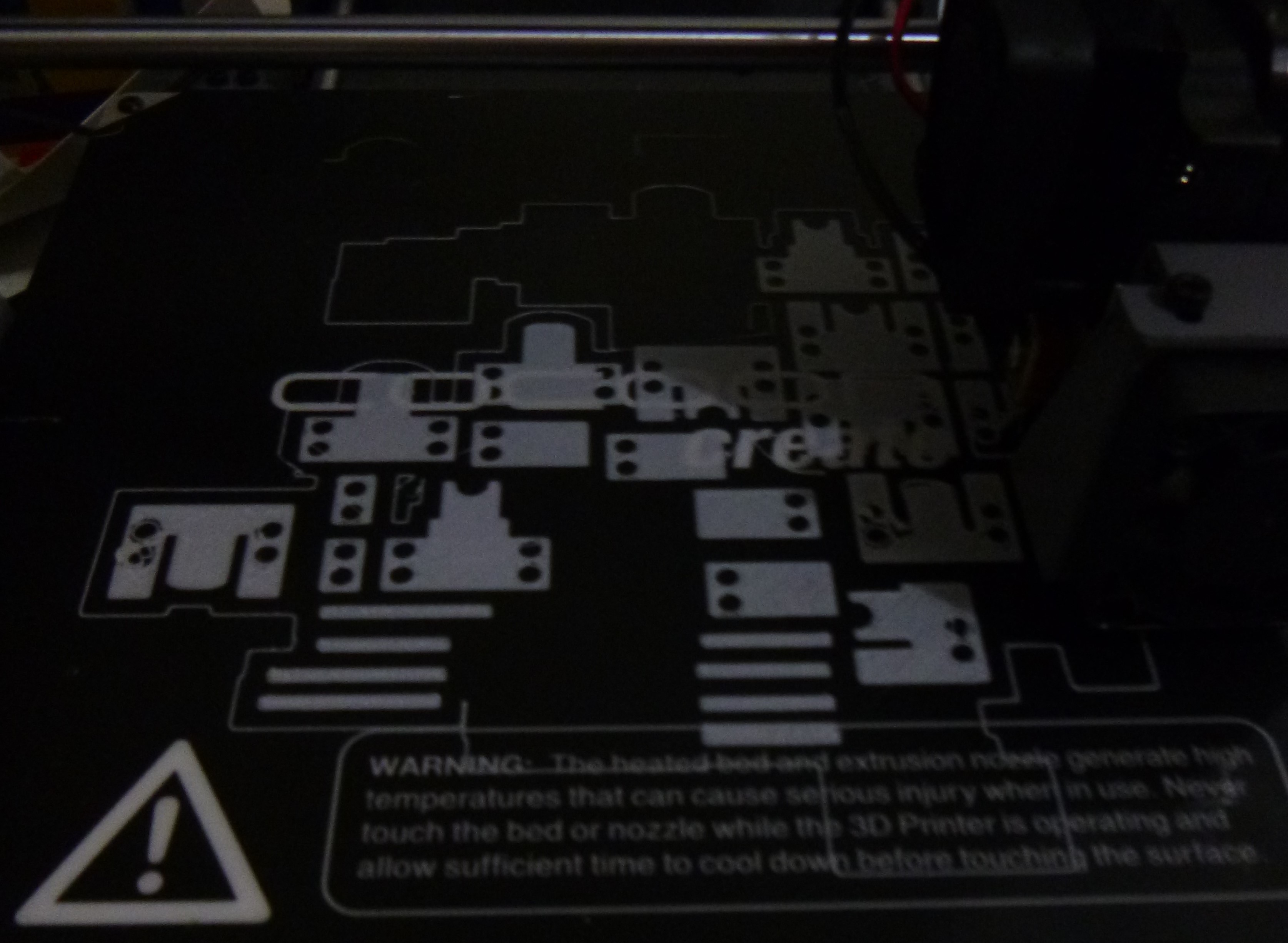
Multiple sections and be added and combined to create a complex whole. Each component of the mold is printed with the thin parts printed flat at 0.1mm layer height to the height of 0.5mm. It would be nicer/better to laser cut these part out of 0.5mm sheets of something, but it is difficult to find a 0.5mm sheet of something and then a laser cutter. Using the tools available these modular molds are designed for this in mind.


 ben.brochtrup
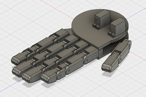

 Jason Cho