 Rui Caldas
INTRODUCTION
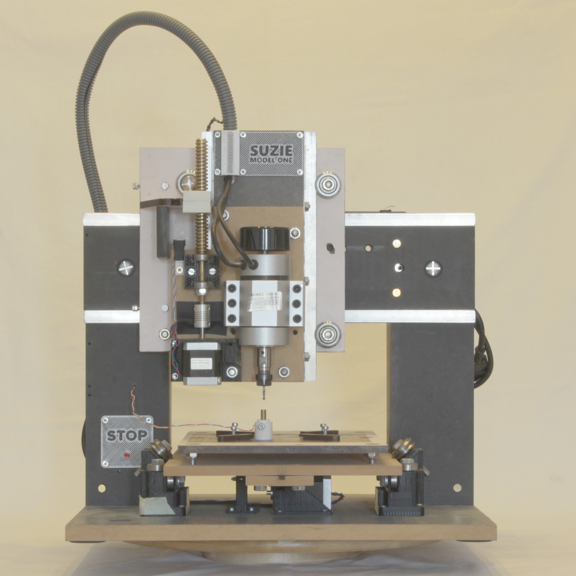
SUZIE MODEL ONE was made to cut PCBs. The objective was to create a rigid machine, accurate and as much automatic as possible. Right now the only manual process needed is changing cutting bits and placing the Z-probe in the right place.
This machine is the result of a trial and error process where several parts were redesigned and rebuilt to get the best result possible. The main problem was rigidity: when the machine is not hard enough it will bend as it is cutting and the result will be a failure. Jitter when cornering is the other main problem. It is possible to reduce speed to avoid that, but time is money, and some kind of cuts work better at the right speed, not slower.
To see more check #suziecnc on Instagram.
The next chapters will show and explain why some decisions were made in the construction and when applicable, what the problems that are there to solve.
DIMENSIONS
External size:
- 46cm width
- 62cm length (43cm not working)
- 58cm height (counting with the cable tube)
Working area is approximately:
20cm width (X)
20cm length (Y)
6cm height (Z)
FRONT VIEW
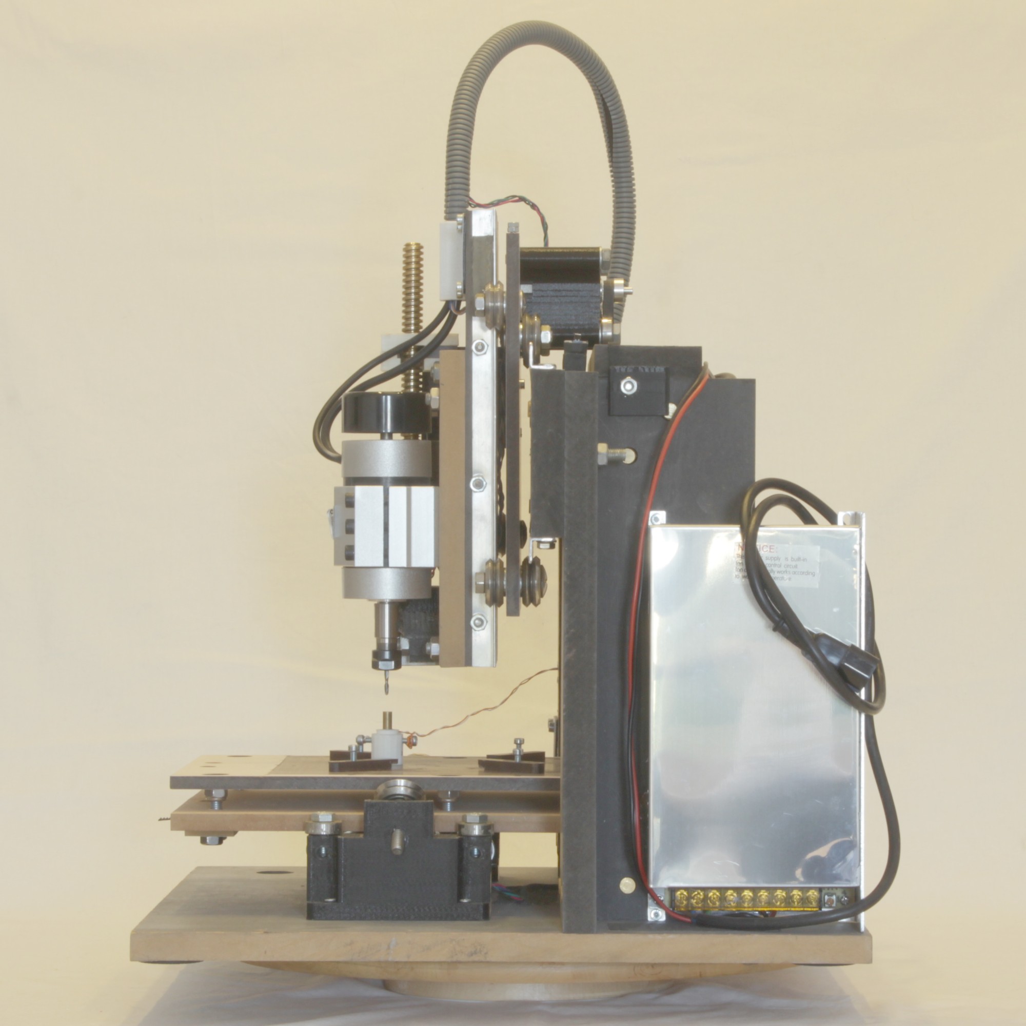
LEFT VIEW

RIGHT VIEW
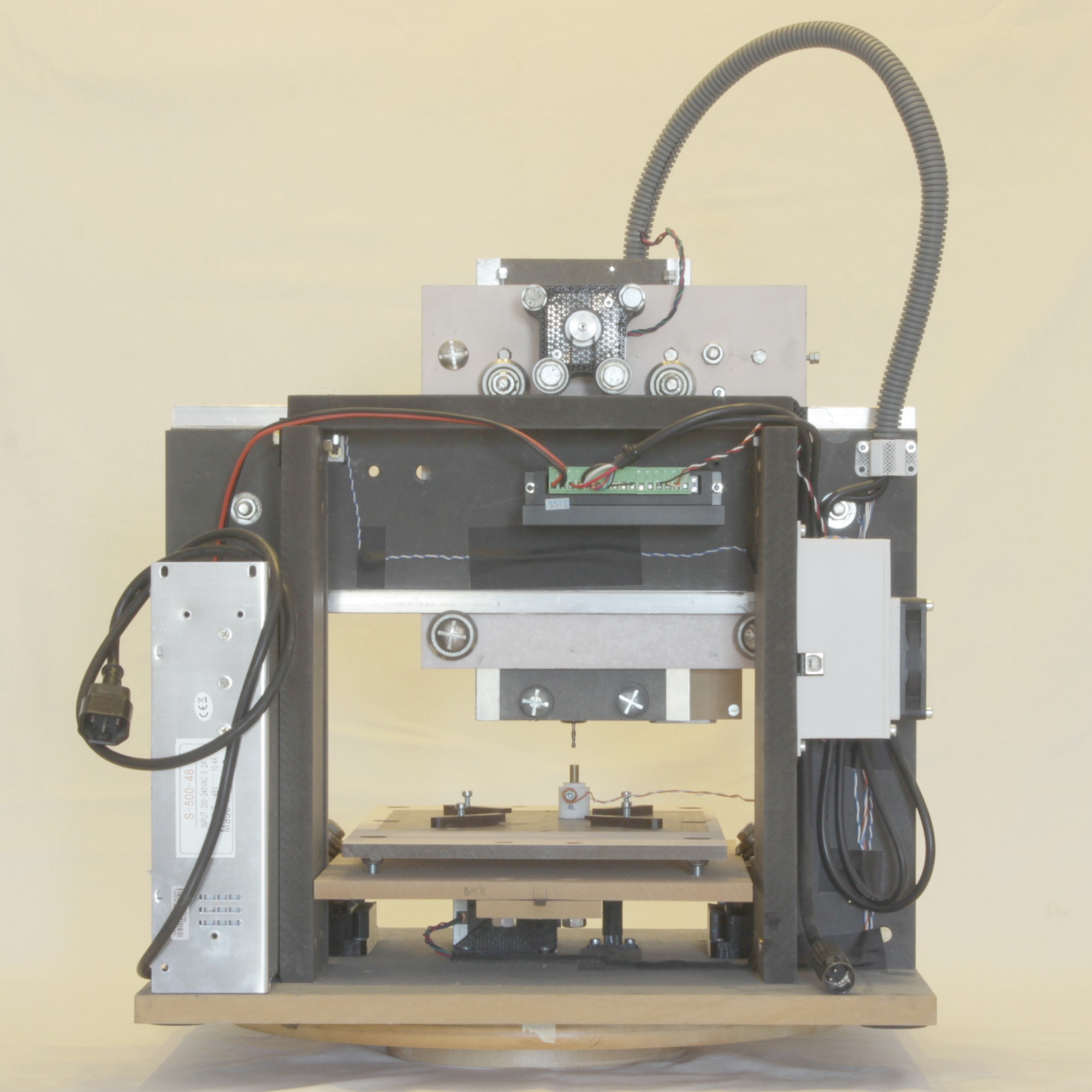
BACK VIEW
TOP VIEW

XY AXIS, STEPPER MOUNTING AND BACKLASH
Backlash "...is a clearance or lost motion in a mechanism caused by gaps between the parts..." - Backlash in Wikipedia
SUZIE has zero backlash on the X and Y axis.
No compensation was made in firmware and always cuts with the right dimensions. This is possible by using belts instead of screw drivers. The lead screw need that little gap to run inside the nut without friction and that need to be compensated. No problem in that but with time, if the nut wear which will cause a constant backlash that needs to be configure in firmware, but if the lead screw wear the problem is bigger just because the normal operation of a CNC machine uses different segments of the lead screw with different speeds and forces; this means that the wear will not be even and impossible to compensate.
The belts are strong enough to apply forces even to cut metal and if properly stretched with no noticeable elasticity.
Both axis on SUZIE uses the same technique to transfer the force from the stepper to the moving part but with a big difference on how the belt and stepper are mounted. In both the belt do not create a loop like in a 3d printer for example; the mechanism for that is bigger and wast more space. Here the belt is open, fixed in both ends and the stepper runs on it as a rack wheel.
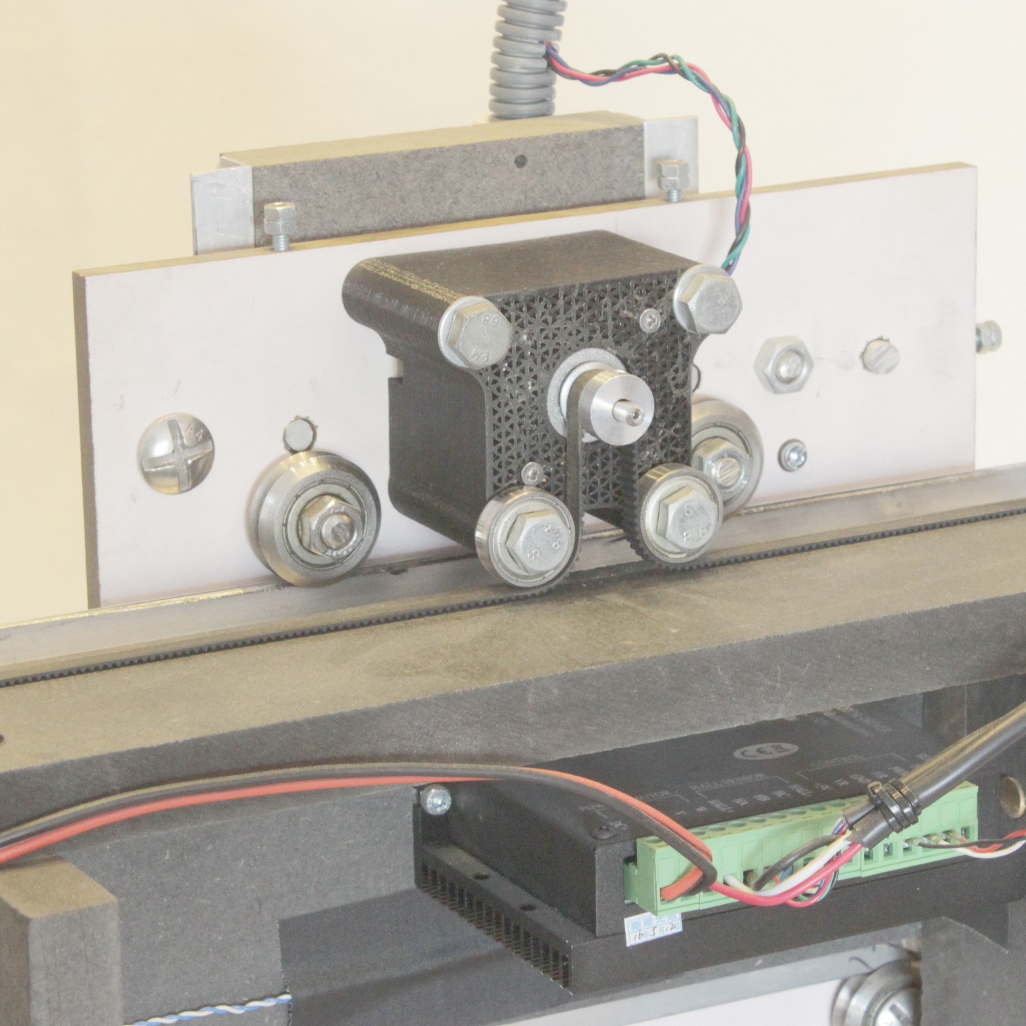
The X car has the stepper attached and the belt is fixed on the machine. The stepper moves with the car.
X STEPPER AND BELT
The Y tray uses the same concept but with a fixed stepper and a moving belt. Is exactly he opposite of the X axis. With this solution another possibility is available: the length of the Y tray is virtually infinite and can be altered as demanded without changing the machine's design. That is also possible because the rail is on the moving tray and the bearing are also fixed to the bottom of the machine structure.
Y TRAY WITH BELT (view from the bottom)
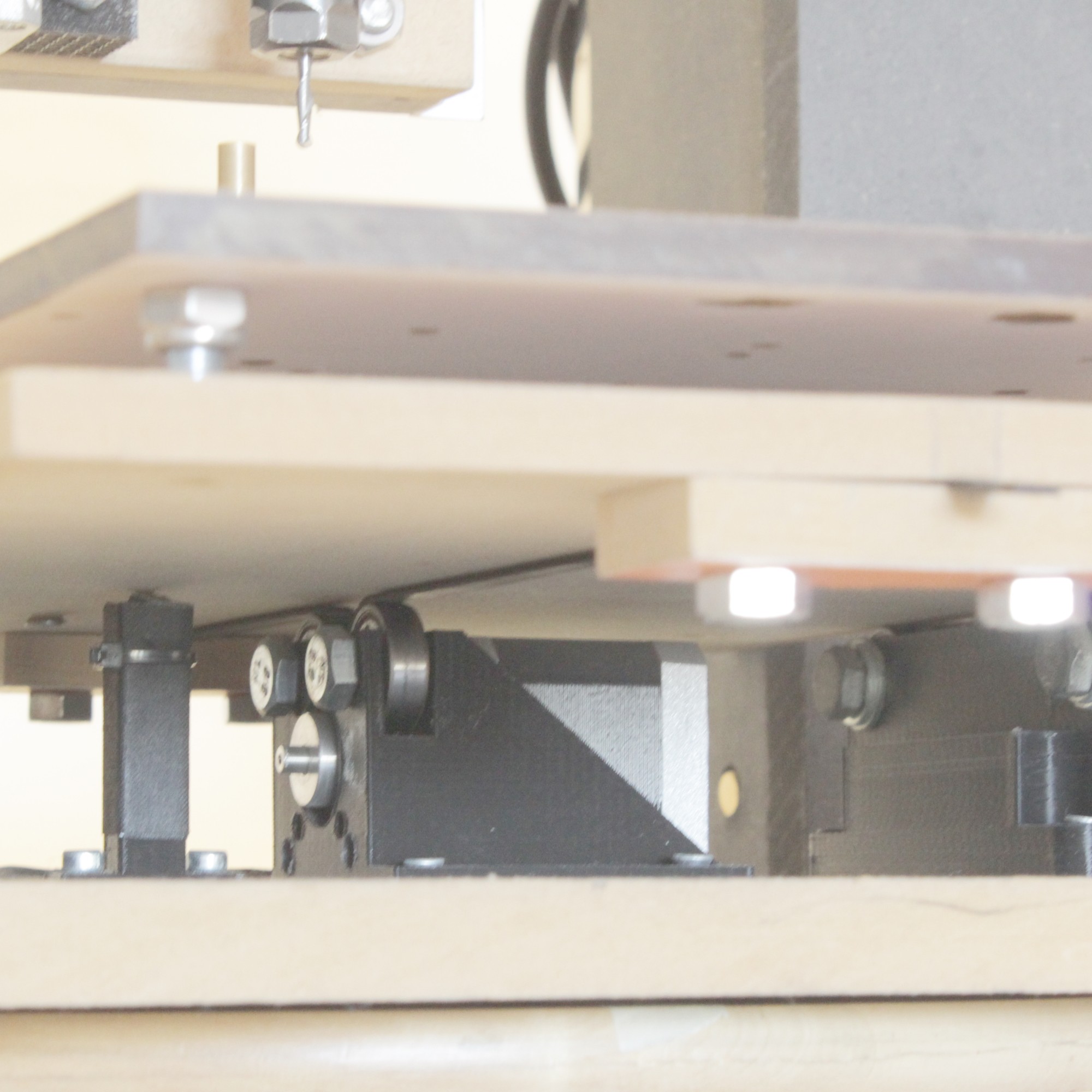
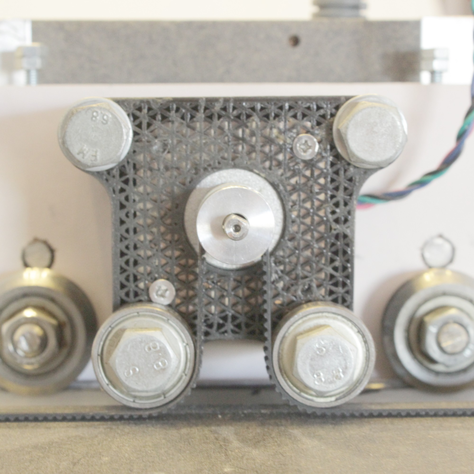
Y TRAY BEARING SUPPORT
This picture show the Y bearings support part. This one (left side) and the other which only the top bearing is visible, are aligned with the X car movement and directly below and centered with the spindle. This means that all the down and sideways forces will be transmitted to the base in a compression way. This allow the support to act very rigid and to sustain lot of force. As we can imagine with this picture, the length of the tray is not important for the mechanics and doesn't need to have any imposed limit (not entirely true) - the limit could be the software, tray fabrication or belt maximum length - but for example, it's perfectly possible to add an 1 meter long tray for a special work.
Z AXIS AND LEAD SCREW
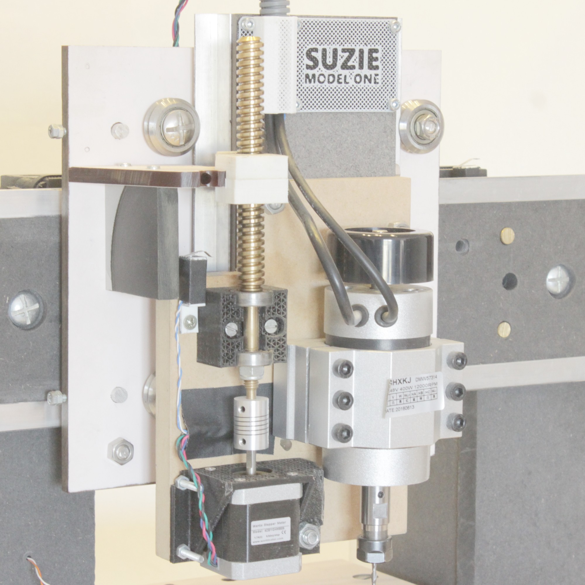
Using a belt configuration in this axis has a huge problem. The stepper need to be in constant load and in a power failure situation the spindle would just plunge into the work, maybe damaging the bit, the motor or ever the work and tray. The solution here is obvious: lead screw.
This lead screw and nut were custom built to this machine. The screw has the necessary length, space for the bearings, locking nut, and connection to the stepper. It was made on an old manual imperial lathe in a metric configuration. The only problem is that the synchronization wheel doesn't work in metric, so a very special way of using the lathe was needed to make this screw. The nut was 3D printed.
This system do not have backlash because the 3d printed nut was made with no gap (it only runs cause lots of oil) but the all XZ cars configuration is very flexible. What maintains the spindle in its position is its weight. If we push it upwards by hand we can move it 2 to 3 millimeters just by bending all the rails a bit. The only mechanical way to solve this is to increase the machine's rigidity. The other solution is slowing down the plunge speed. Don't forget that the cutting process is lateral on the X and Y axis, so if the plunge speed is not very fast, the weight of the Z car and spindle will force the cut to the correct position. In SUZIE's case, the machine's maximum speed of plunging is ok to cut soft materials, so no slowing down needed and only had to slow it down when cutted metal (brass).
3D PRINTED PARTS
This machine was only possible using 3d printed parts. The tools I had access to make the machine were not suitable to build complex parts by hand like the steppers supports, for example. All of the parts were designed and printed more than one time to accommodate special functions or structural improvements. These parts reduce the rigidity of the machine but allows to be more compact.
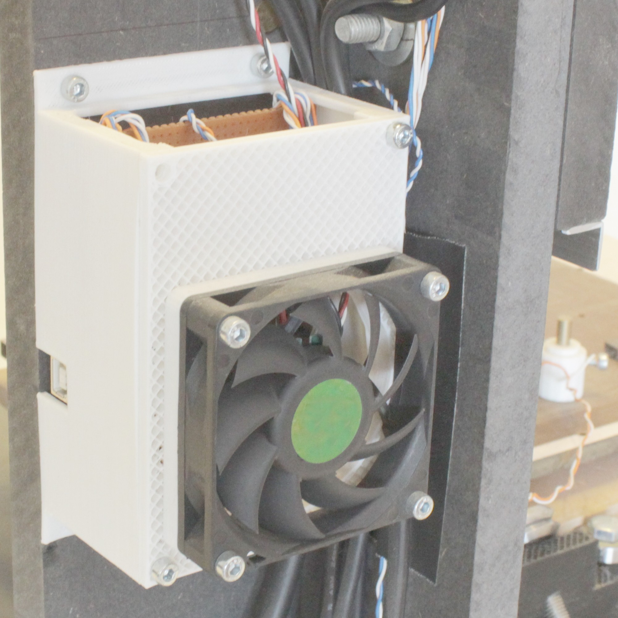
X STEPPER MOTOR HOUSING
ARDUINO CASE
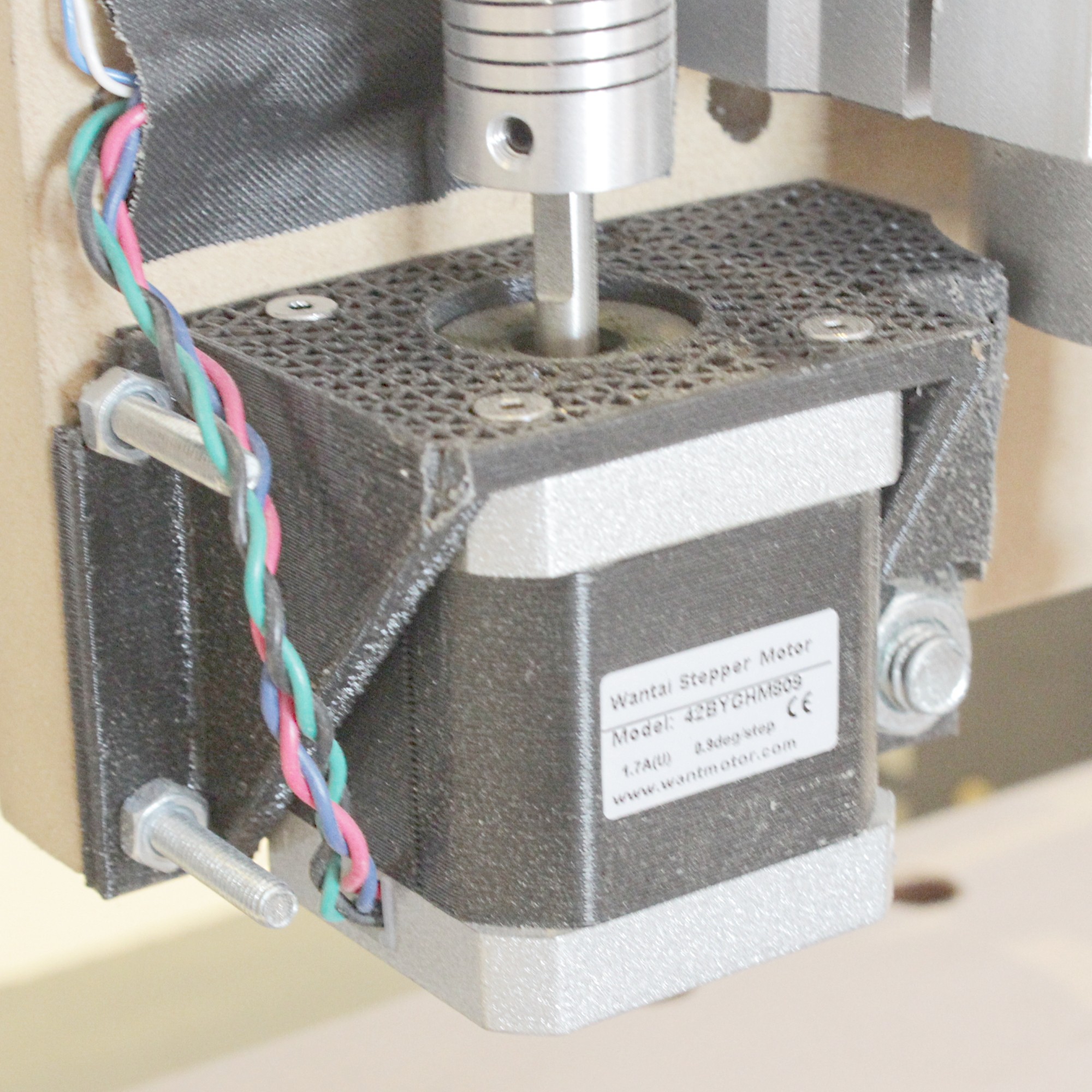
Z AXIS STEPPER SUPPORT
ARDUINO, GRBL, SHIELD, SPINDLE AND PROBE
SUZIE's brain is an Arduino Uno, running the GRBL firmware.
There are several commercial shields to GRBL but in this case was more a challenge case. The first shield I have built used the L298N and L297 combination to drive the steppers. It was hot and loud. Later with the Polulu drivers, the system was redesign to be improved.
ARDUINO GRBL CUSTOM BUILT SHIELD
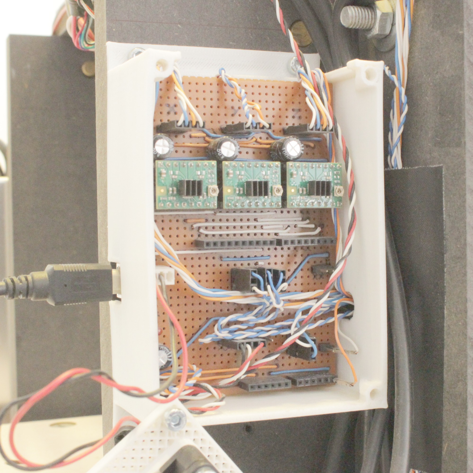
The circuit is made on a prototype board and has almost all the GRBL connections available. Since the addition of this board, the machine was able to work for a much longer time without overheating and making less noise because these drivers have microstepping. Currently the firmware is updated to the GRBL 1.1f and runs very smoothly.
Another recent addition was a proper spindle brushless motor. This is now controlled by the Arduino and is much more silent compared with the dremel like drill I had in the first iteration.
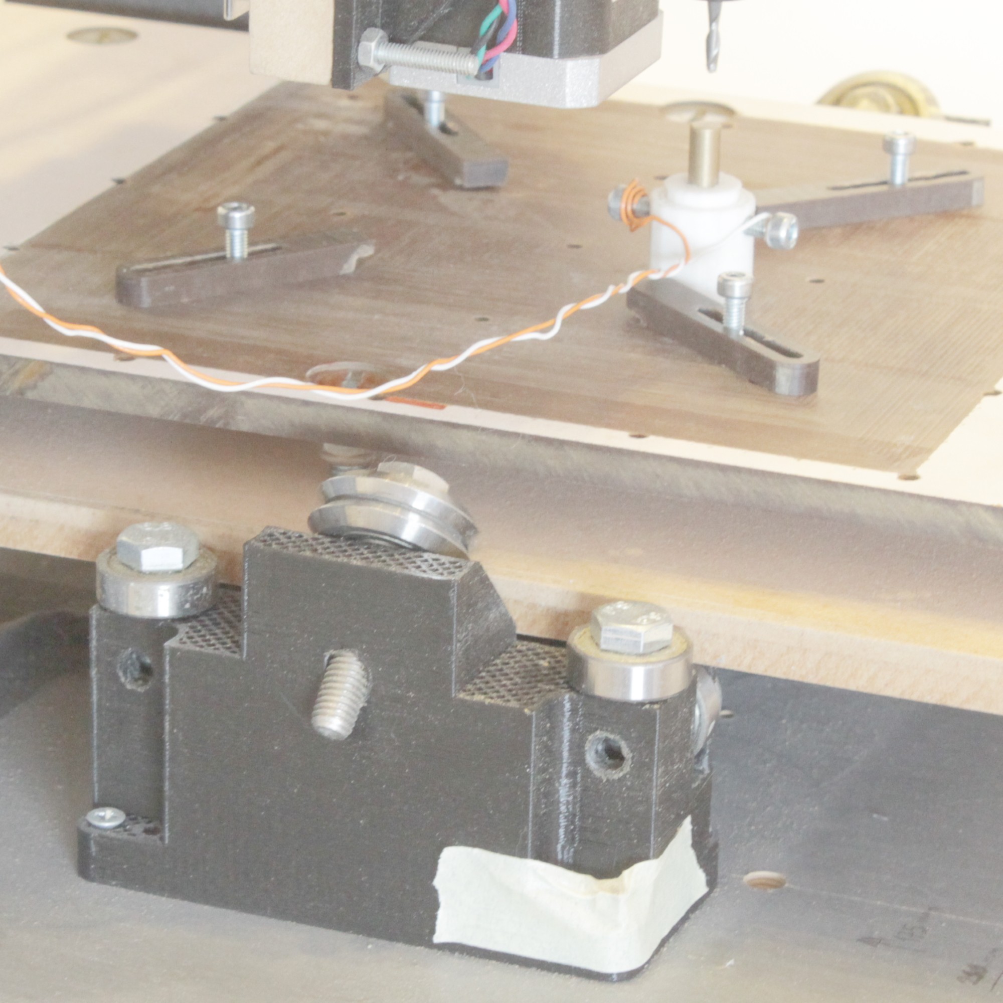
PROBE
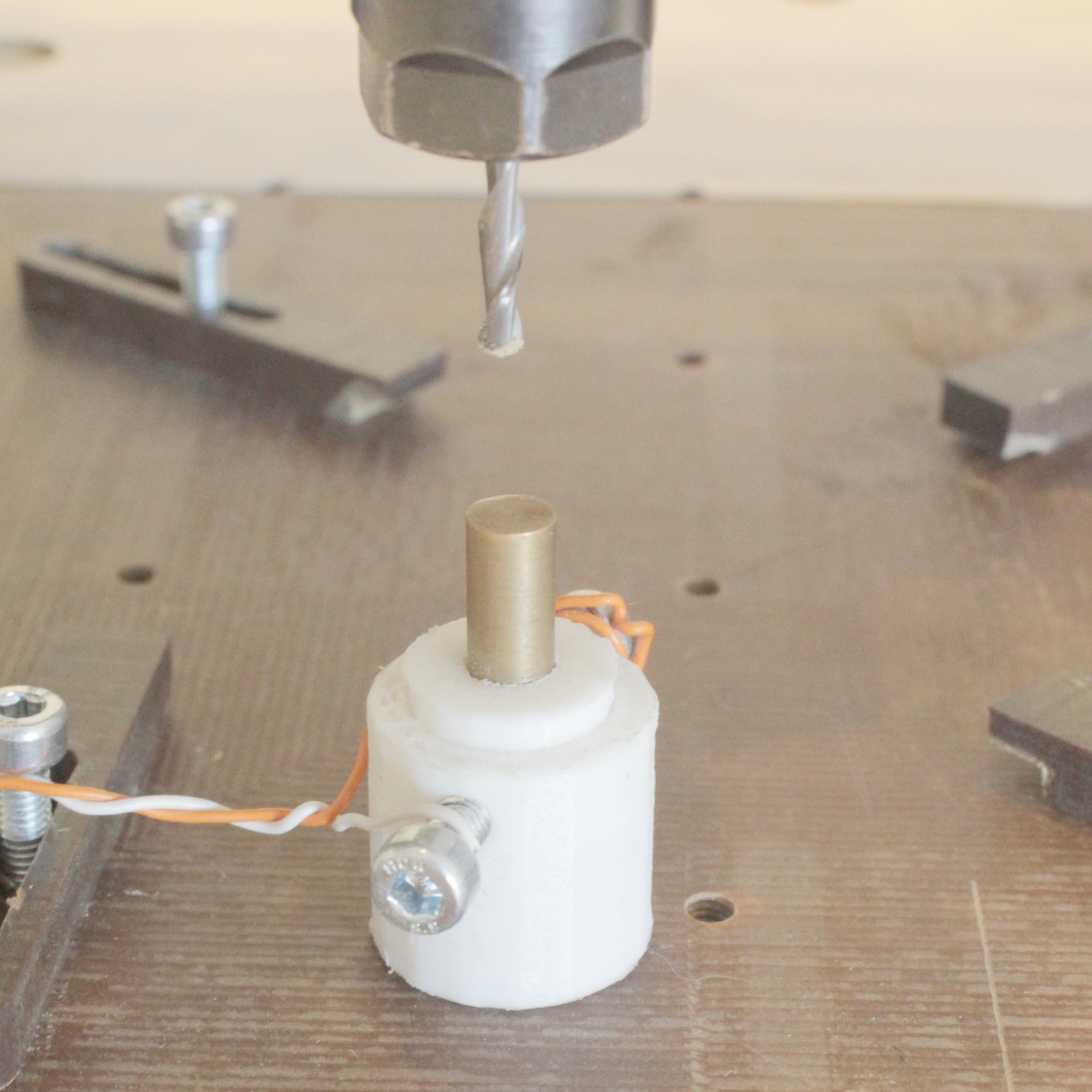
This probe was made to measure only the Z axis. The X and Y kind of probe is more complex to make by hand and it will be a challenge to other time. With the probe, SUZIE can be very precise in locating the cutting bit tip which is crucial to PCB milling. It is a always ON button and when the bit pulls it down, disconnect the two wires and signals GRBL the position. Its repeatability is very accurate.
CONCLUSION
SUZIE MODEL ONE was an excellent way to learn how to make a CNC machine. Many problems were solved, many characteristics were improved and I can say for sure: its done!
Anything that is needed to improve no longer makes sense in this structure.
SUZIE MODEL TWO will be designed to increase what is good in this design and to radically improve model one's problems. One thing for sure: it will be metal!