 Joe
JoeIn the last log, I determined the two basic requirements for my ideal actuator:
1) 10mm maximum width per actuator
2) Needs to apply ~6mNm of torque to the pick
The design process was lengthy, tedious, and detailed. It took me 3 weeks to arrive at an ideal design, and would probably take me two weeks that I don't have right now to write it all up. Sorry to disappoint, but I'll try to put it together in the future.
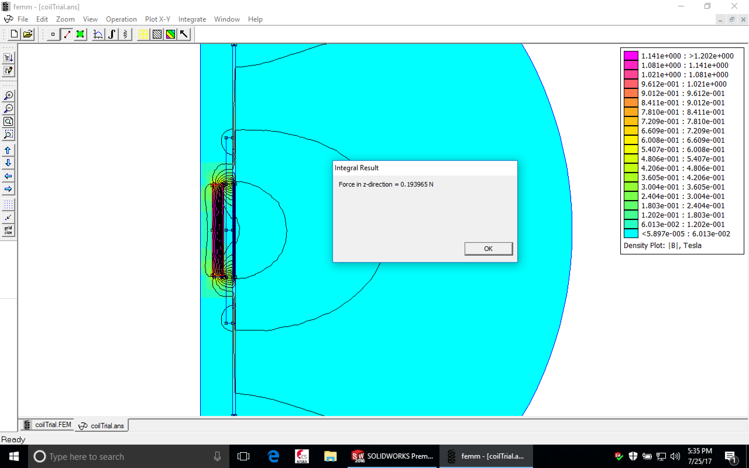
I performed my design analytics using a great free tool called FEMM (http://www.femm.info/wiki/HomePage), which performs analysis of magnetic systems. FEMM supports LUA scripting, so iterating through multiple designs was a (relative) breeze [read: took a lot of time, but it sure beats hand-calculations!]. I was able to see the force generated on the actuator along every position of my plunger magnet, as well as the fields surrounding the actuator.
First thing to do is make a prototype. I hacked together one actuator, and here's the result:
Looks good! Skipping WAY ahead:
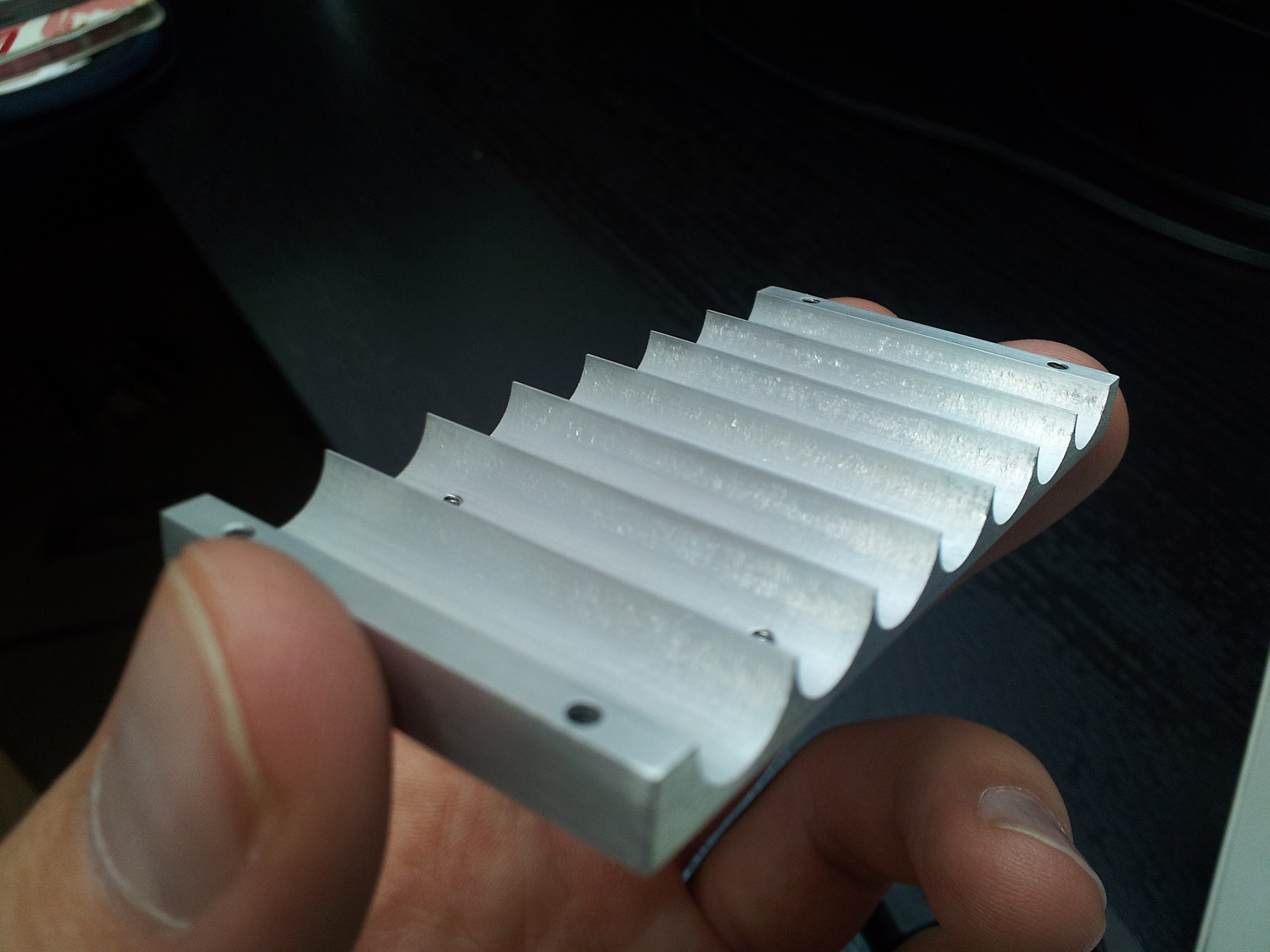
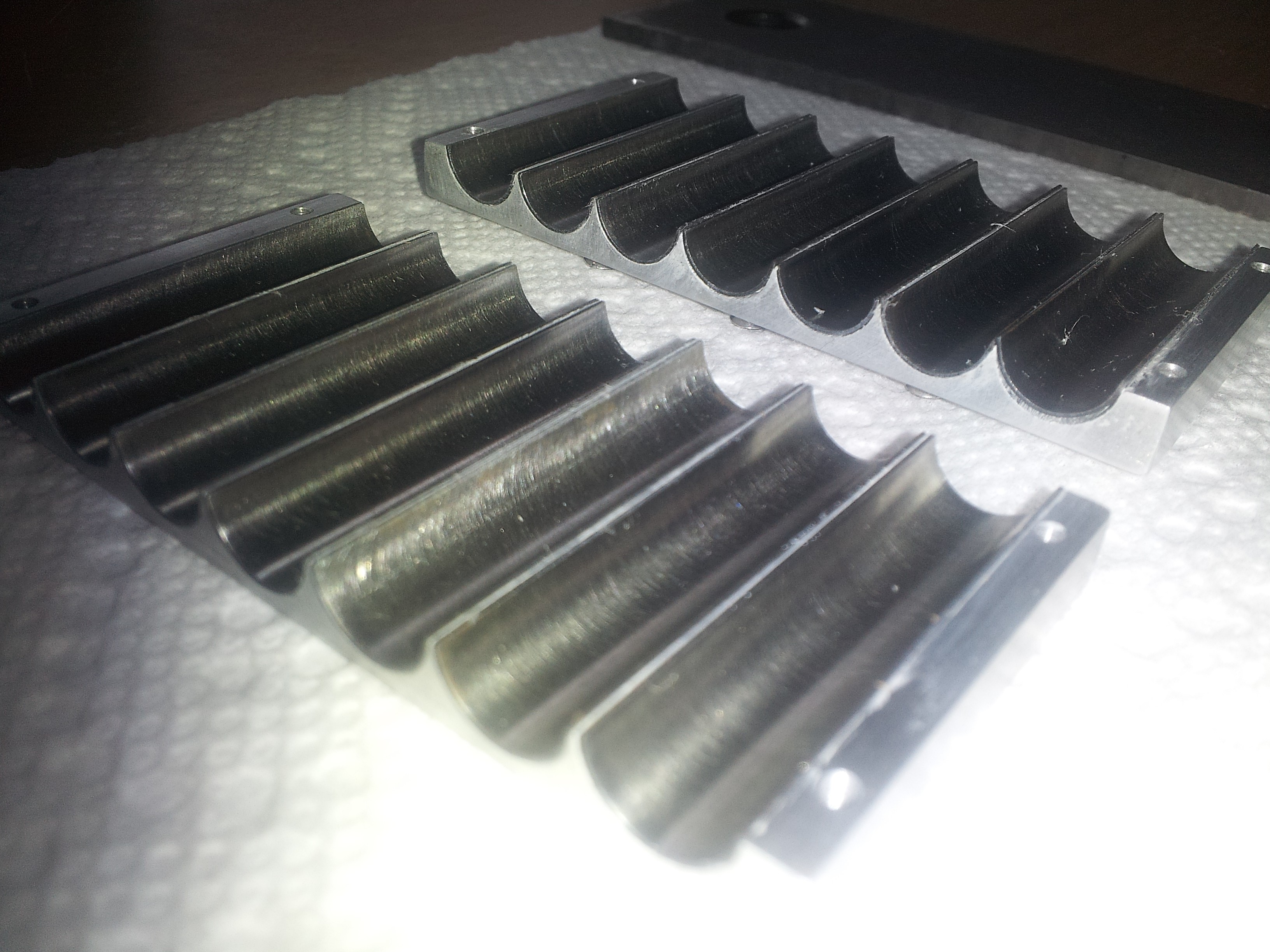
The final design starts with a two-piece (clam-shell) machined aluminum block with a channel for each actuator. Here's one half. The holes are for mounting later...
**** If you noticed there are 7 actuator slots, it's because there are 7 actuators in the design. I'll explain this later, so do your best to not let it bother you.****
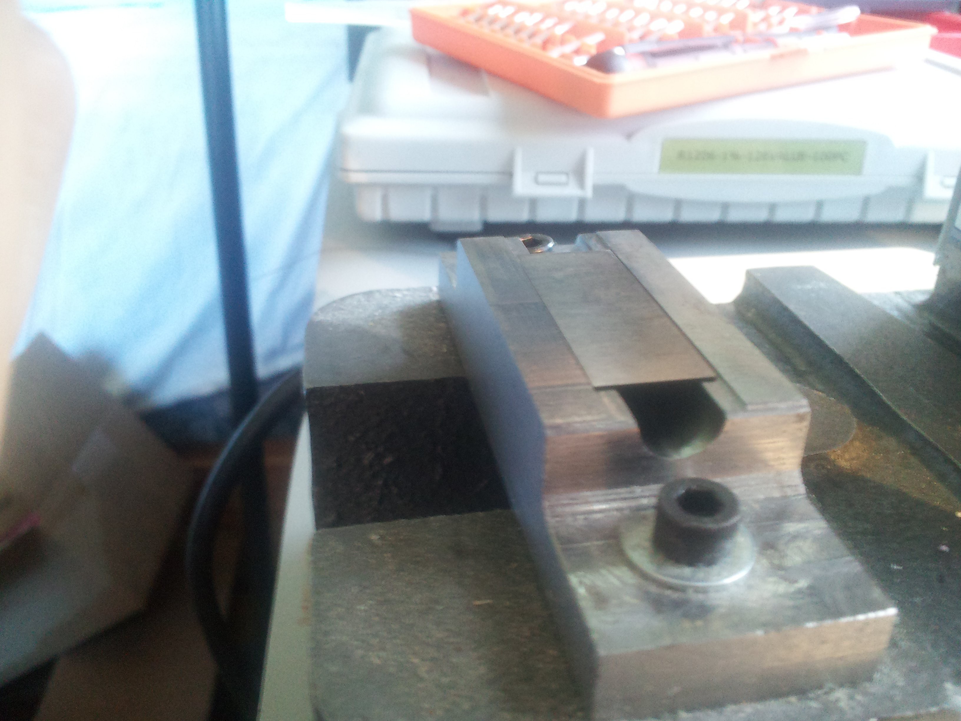
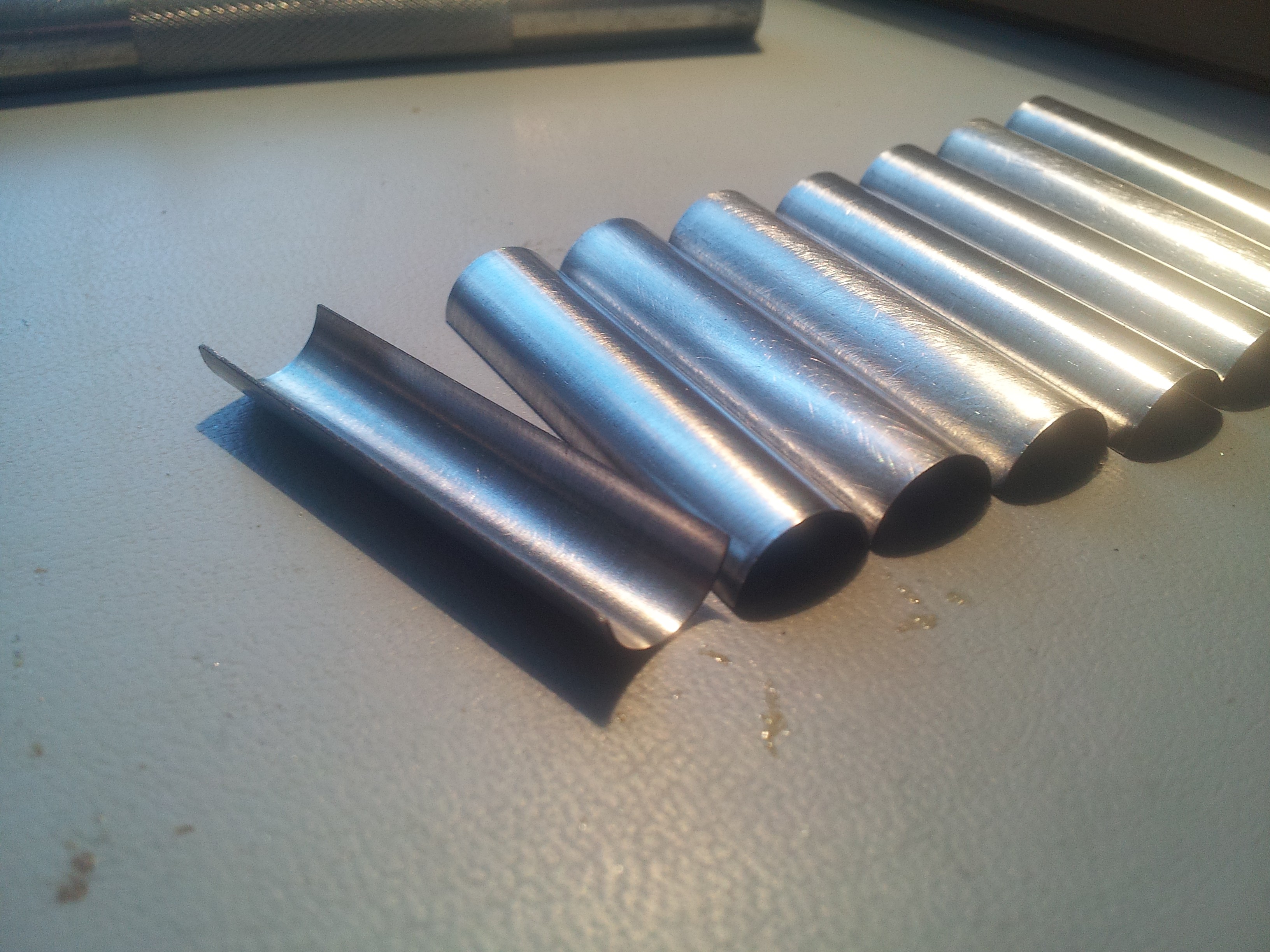
To prevent cross-interaction between plunger magnets, a 15mil layer of magnetic shielding material lines each channel. The shields were cut into rectangles with a sheer, shaped using an arbor press into a custom form and gauge pin, and then glued into place using thermally-conductive epoxy. Here's a flat piece of shield material getting ready to be pressed into shape:
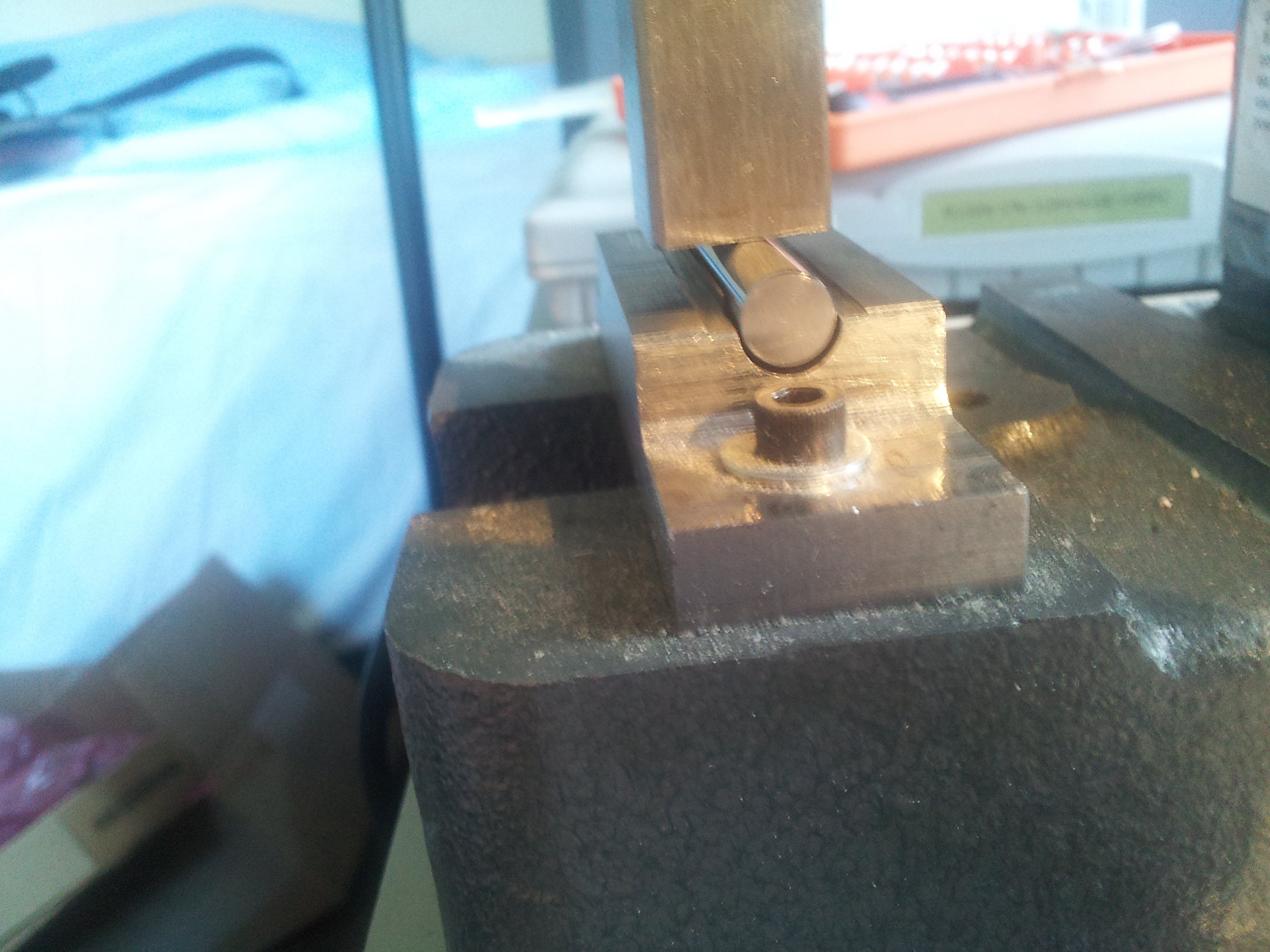
Then we press:
Shaped shields, ready to install:
Shields placed into their channels on the two halves of the actuator block shells. A super thin layer of thermal epoxy went down first:
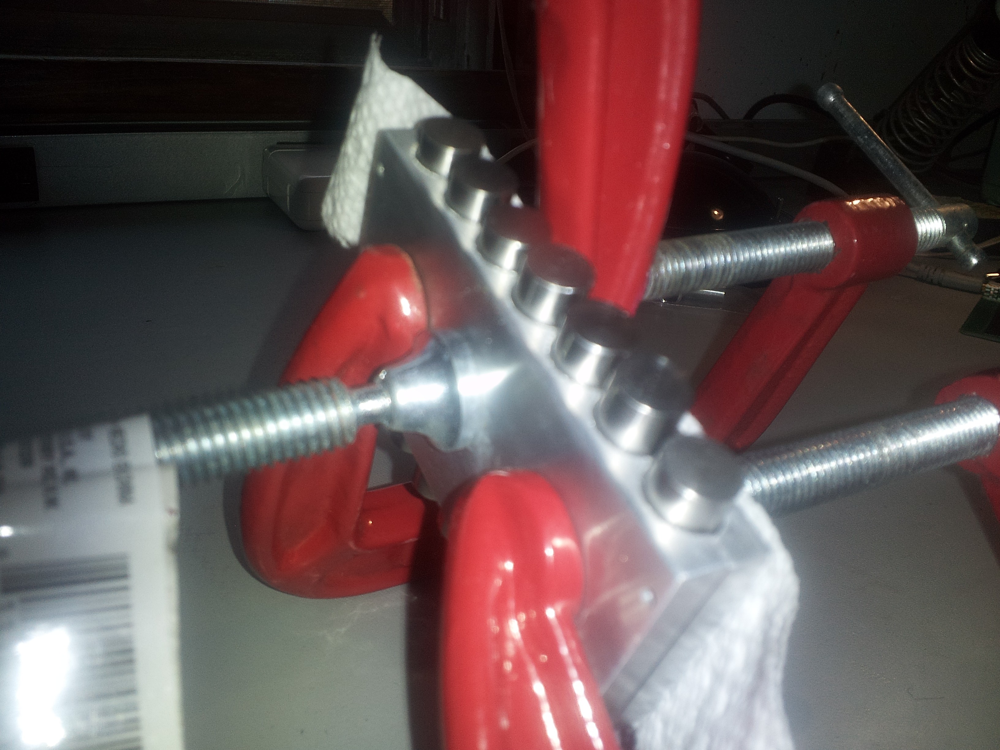
Gauge pins and clamps keep everything precisely in place while the epoxy cures:
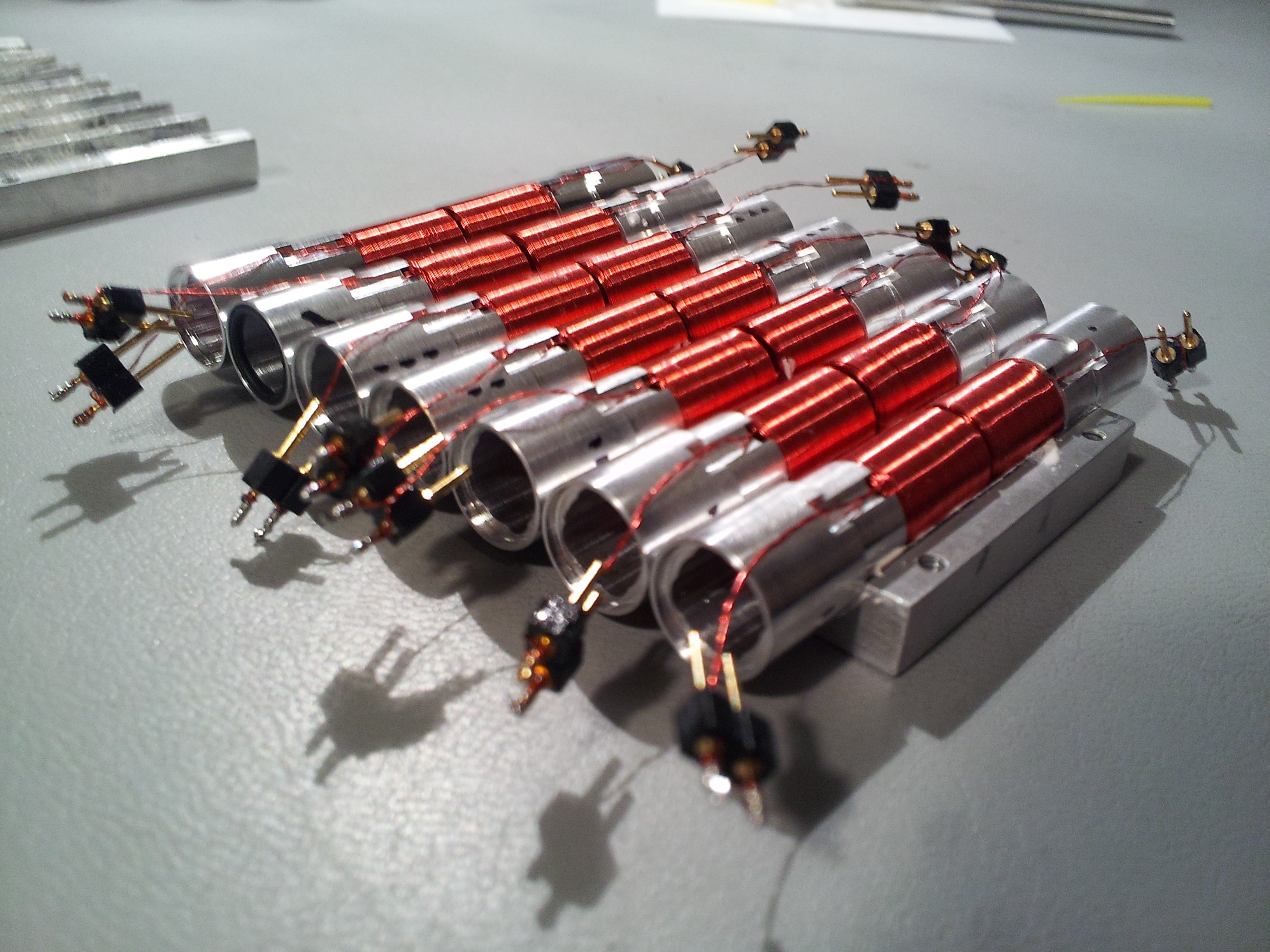
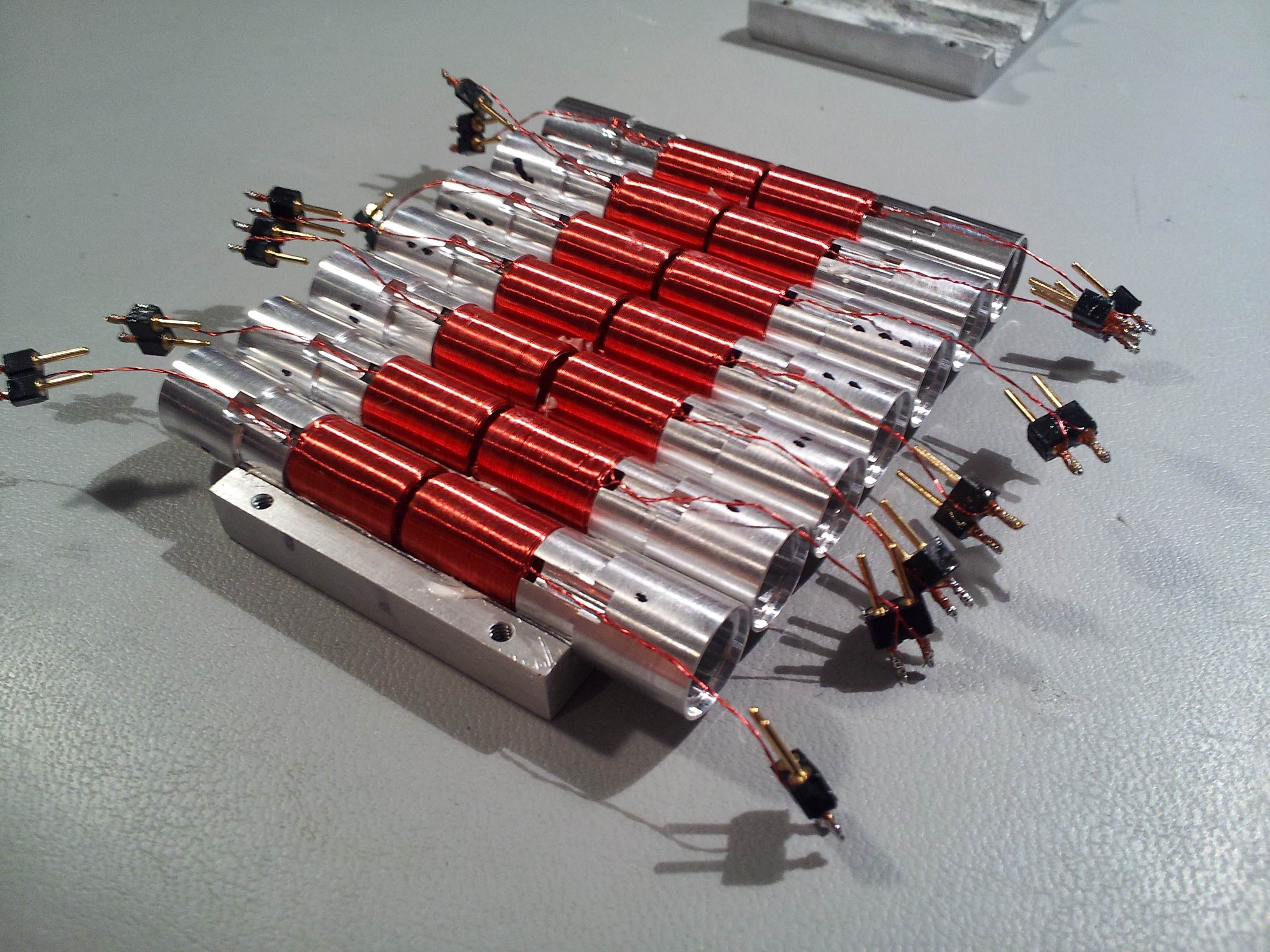
Another layer of glue, and then we place the custom ball bearing races and coils in place. The coils were made by Custom Coils, and they did a killer job. The bearing races were designed by me, and fabricated by Small Parts CNC in California. The plunger will be installed later, and will ride on rubber ball bearings that move in LINEAR channels in the bearing races. Note the wire exit channels that are milled into the bearing races:
A cutaway render showing how the bearing design works:
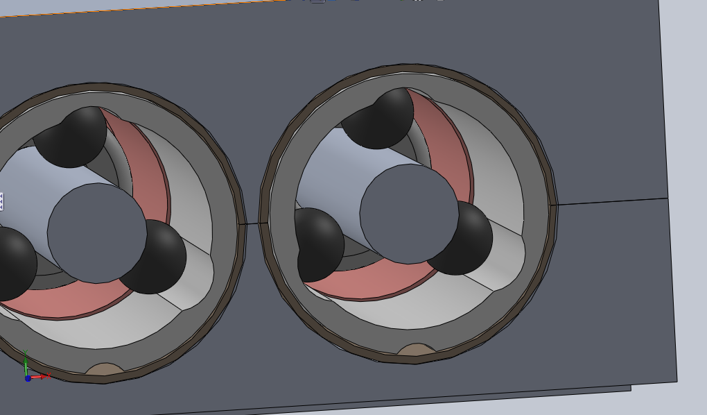
Another view:
The clamps come in again to make sure everything is held in place while the new epoxy sets.
Next the plungers are inserted. The plungers are custom aluminum rods with cylindrical permanent magnets glued in place at their centers, and o-rings + press-fit caps at the ends. All custom machined to perfection. Each plunger rides on 8 rubber ball bearings inside the races.
Check out how smooth and silent the motion is!:
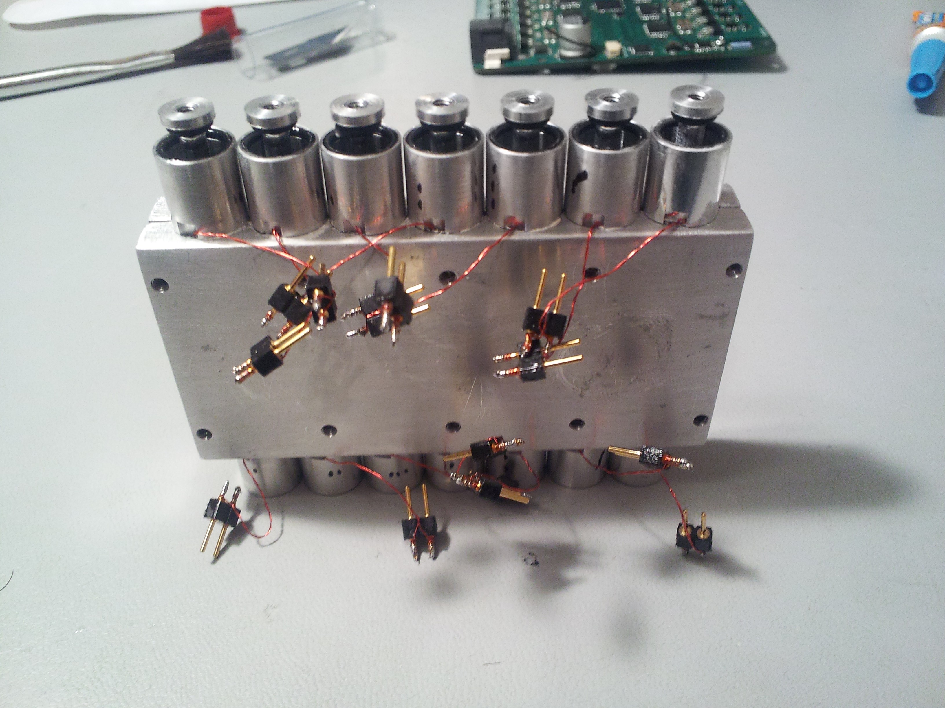
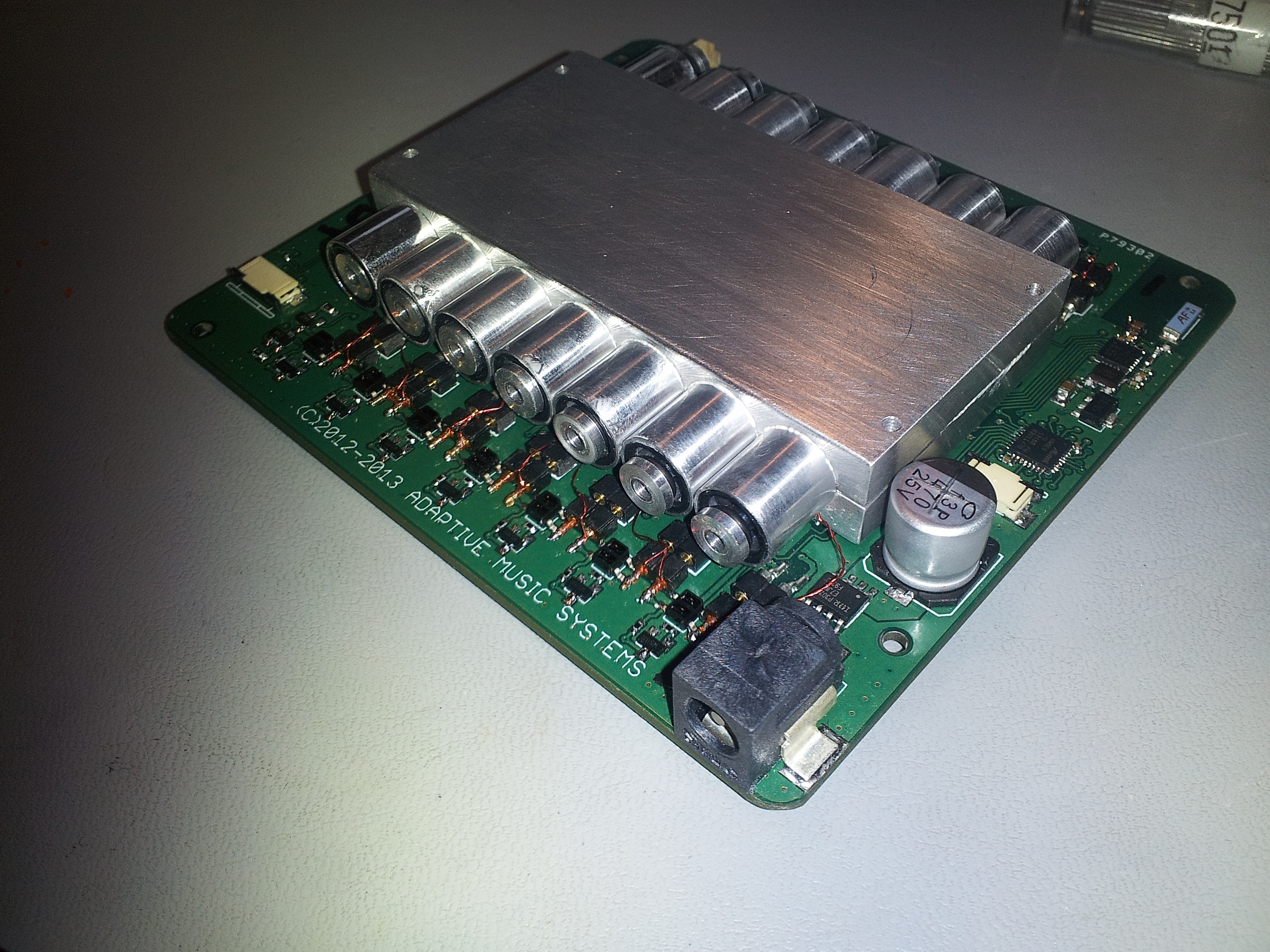
The actuator block gets mounted directly to the control PCB (more on that later), and acts as a heatsink for the power electronics. Thermal paste (not epoxy) goes onto the power IC's first!
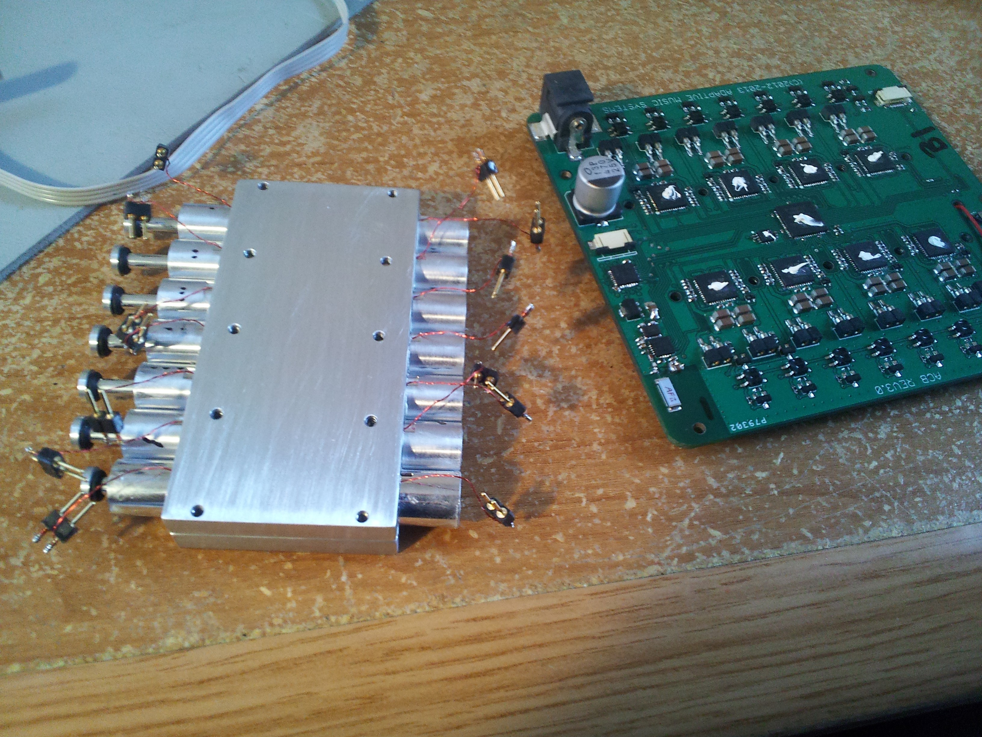
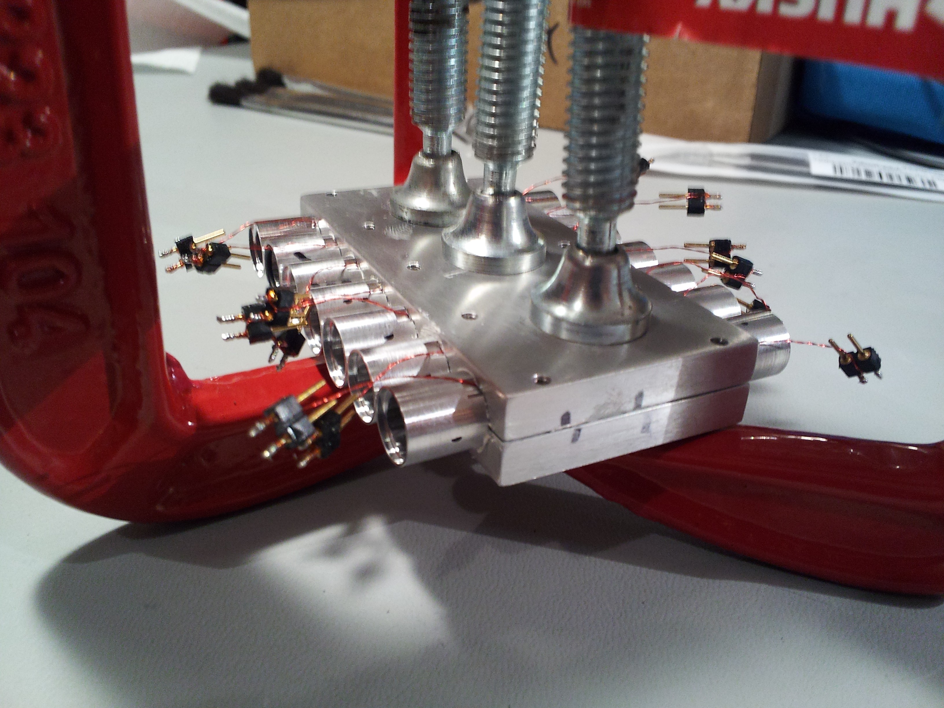
Actuator Block mounted to the control PCB, and all of the coils connected up:
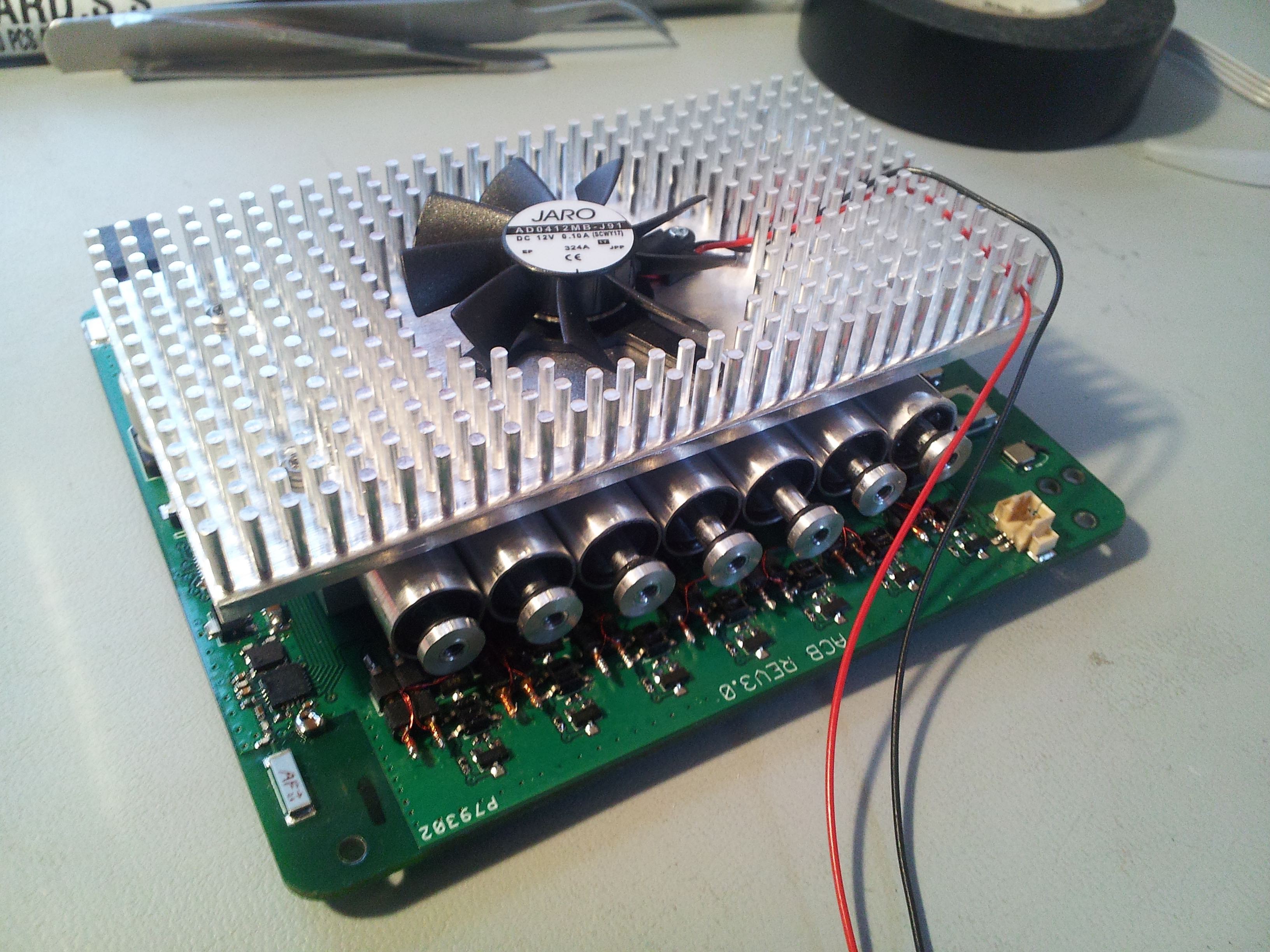
A custom heatsink bolts to the aluminum block, and keeps things running cool. The fan rarely necessary, but is temperature activated and super quiet anyway.
Now we throw it in the enclosure:
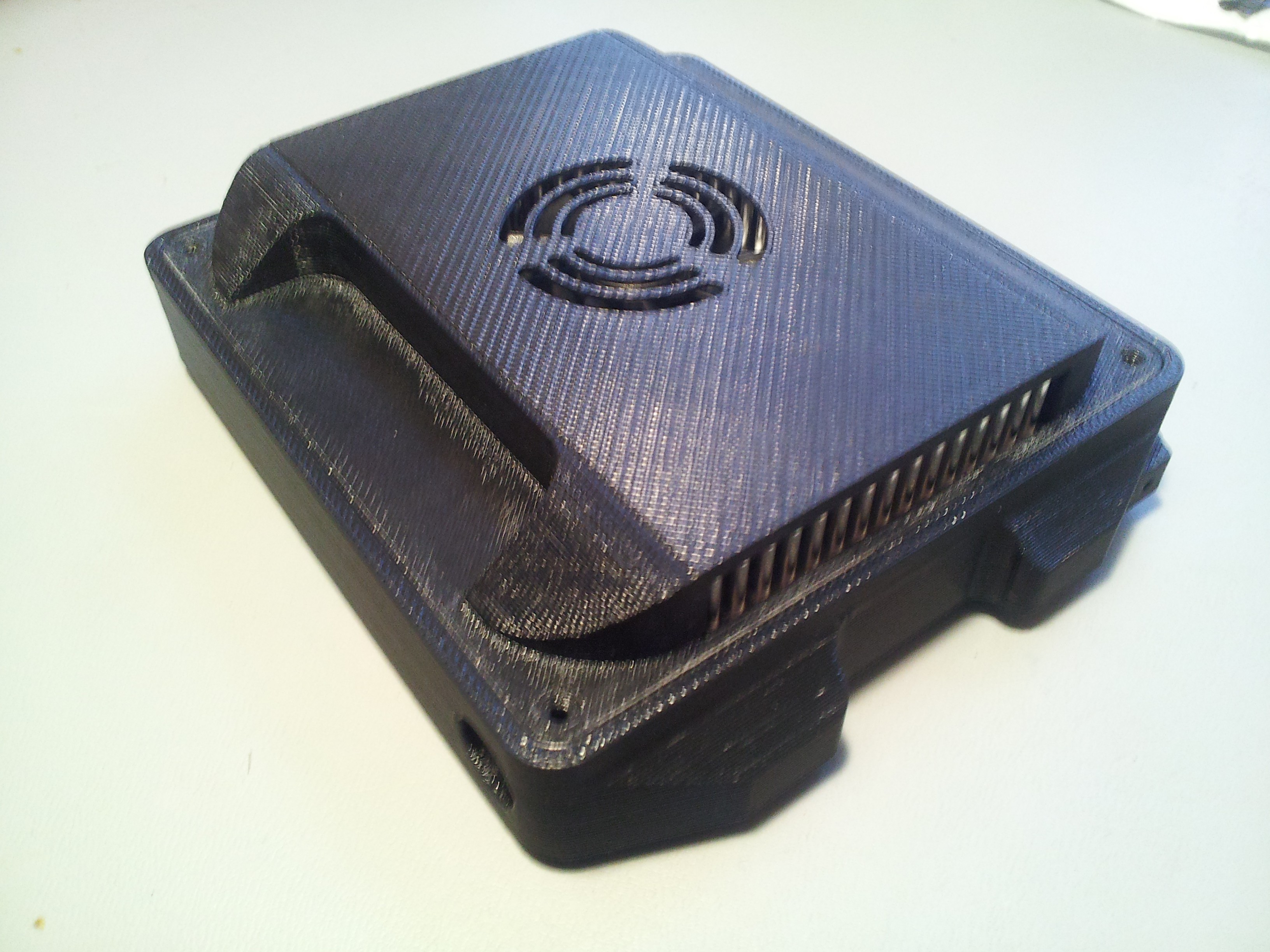
The whole thing weighs 10.5oz.
Here's a quick video of the system initializing / demonstrating control. There was one small glitch in the firmware that caused odd motion on one actuator, but you get the idea:
Discussions
Become a Hackaday.io Member
Create an account to leave a comment. Already have an account? Log In.