 David Boucher
Full details will be added here eventually but for now, here is my plan for the main components:
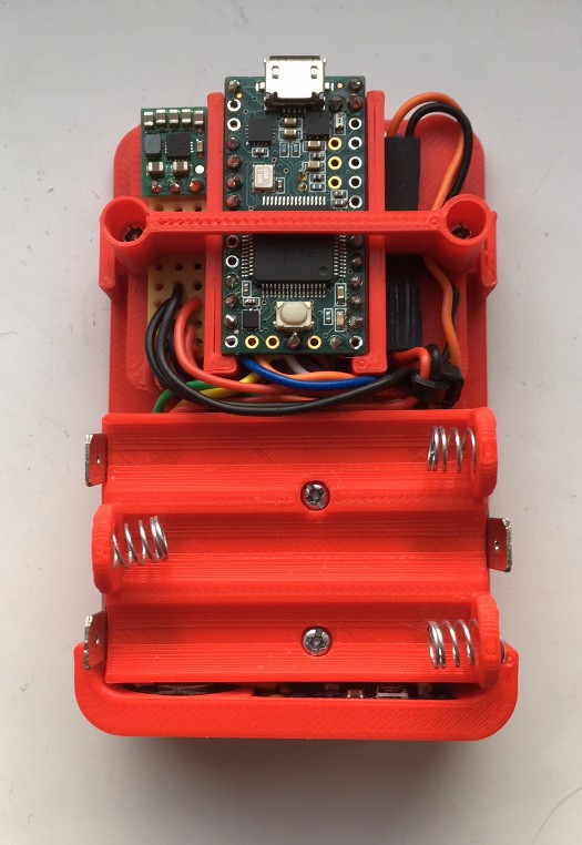
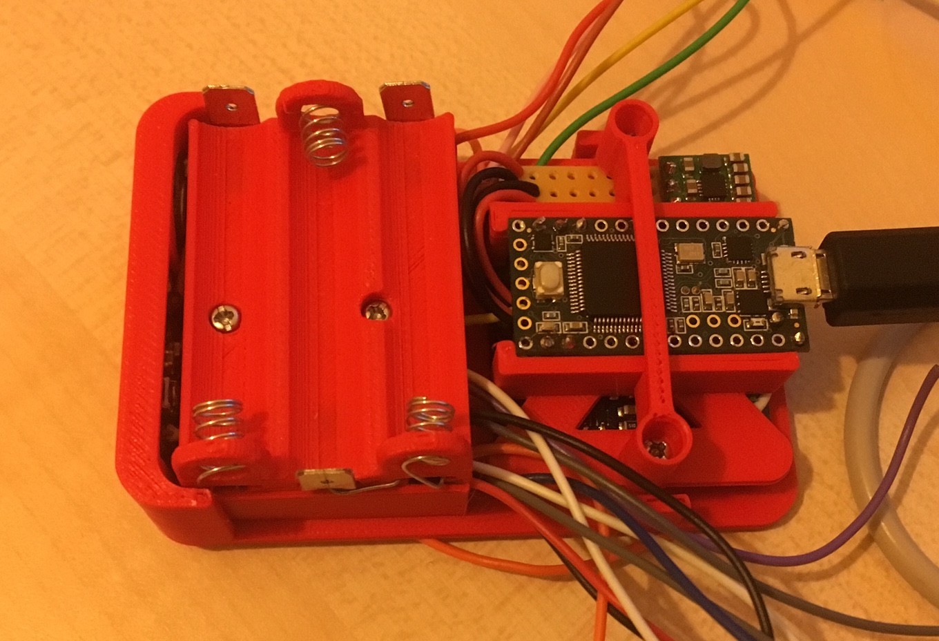
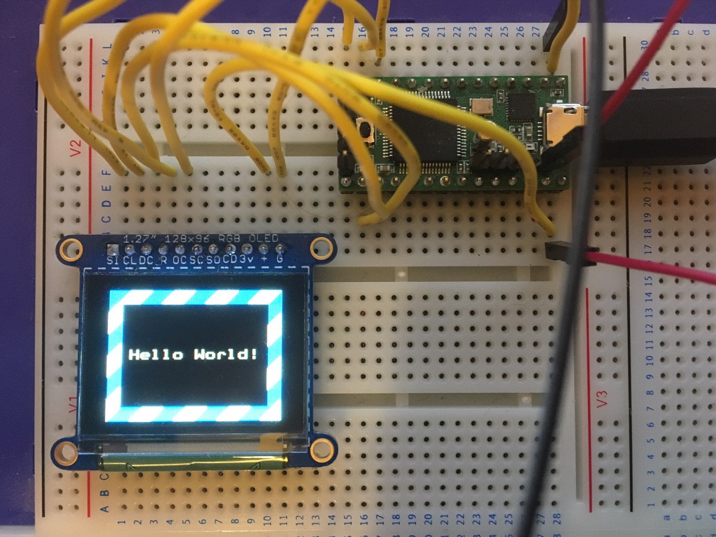
- Teensy 3.2 (From PJRC, see https://www.pjrc.com/store/teensy32.html).
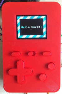
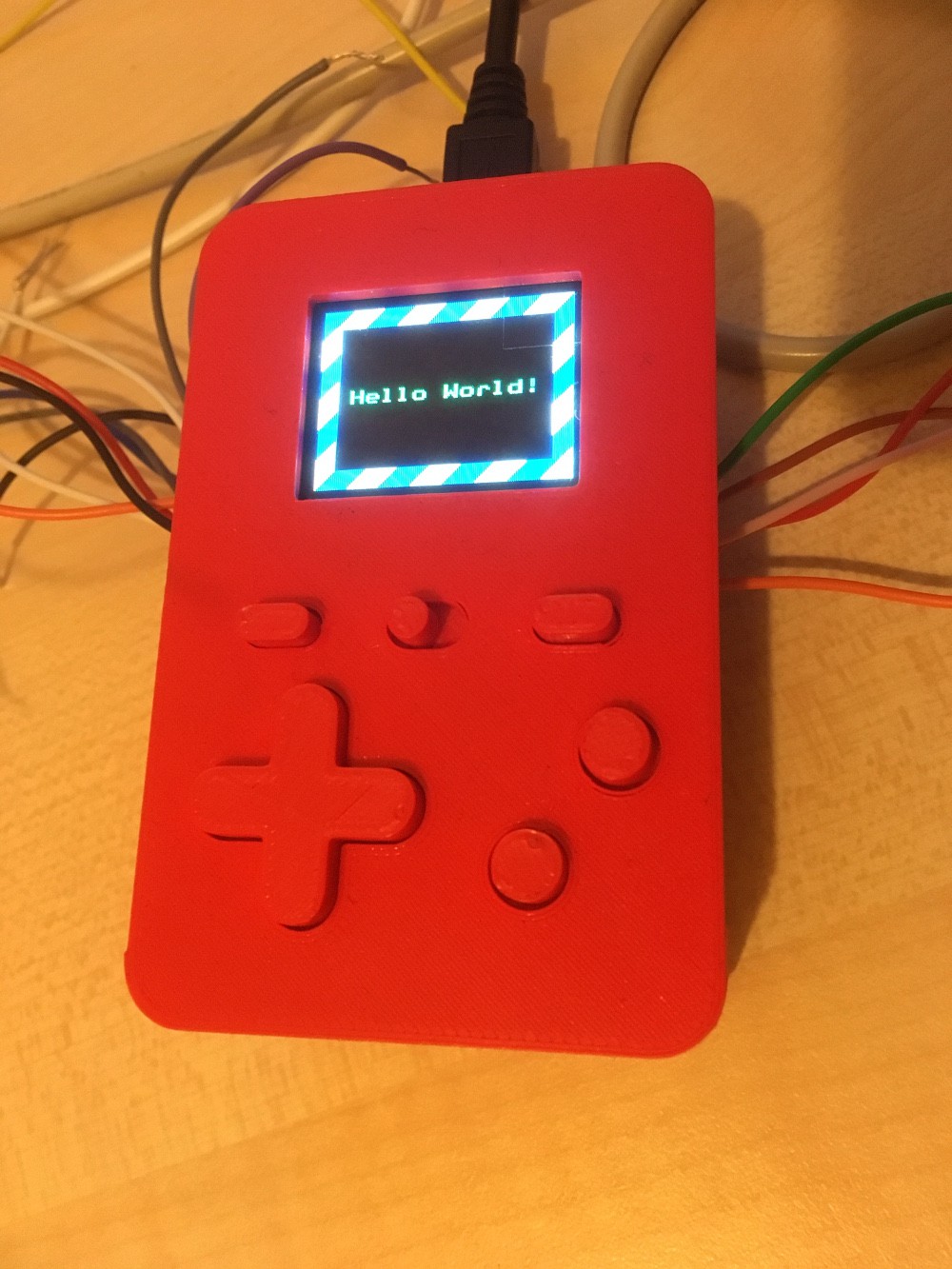
- 128x96 pixel OLED screen (From Adafruit, see https://www.adafruit.com/product/1673).
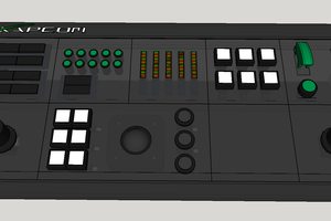
- 8x push buttons (From Adafruit, see https://thepihut.com/products/adafruit-soft-tactile-button-8mm-x-10).
- An amplifier for the above (Also from Adafruit, see https://www.adafruit.com/product/2130).
- Voltage regulator.
- Power switch.
- A speaker.
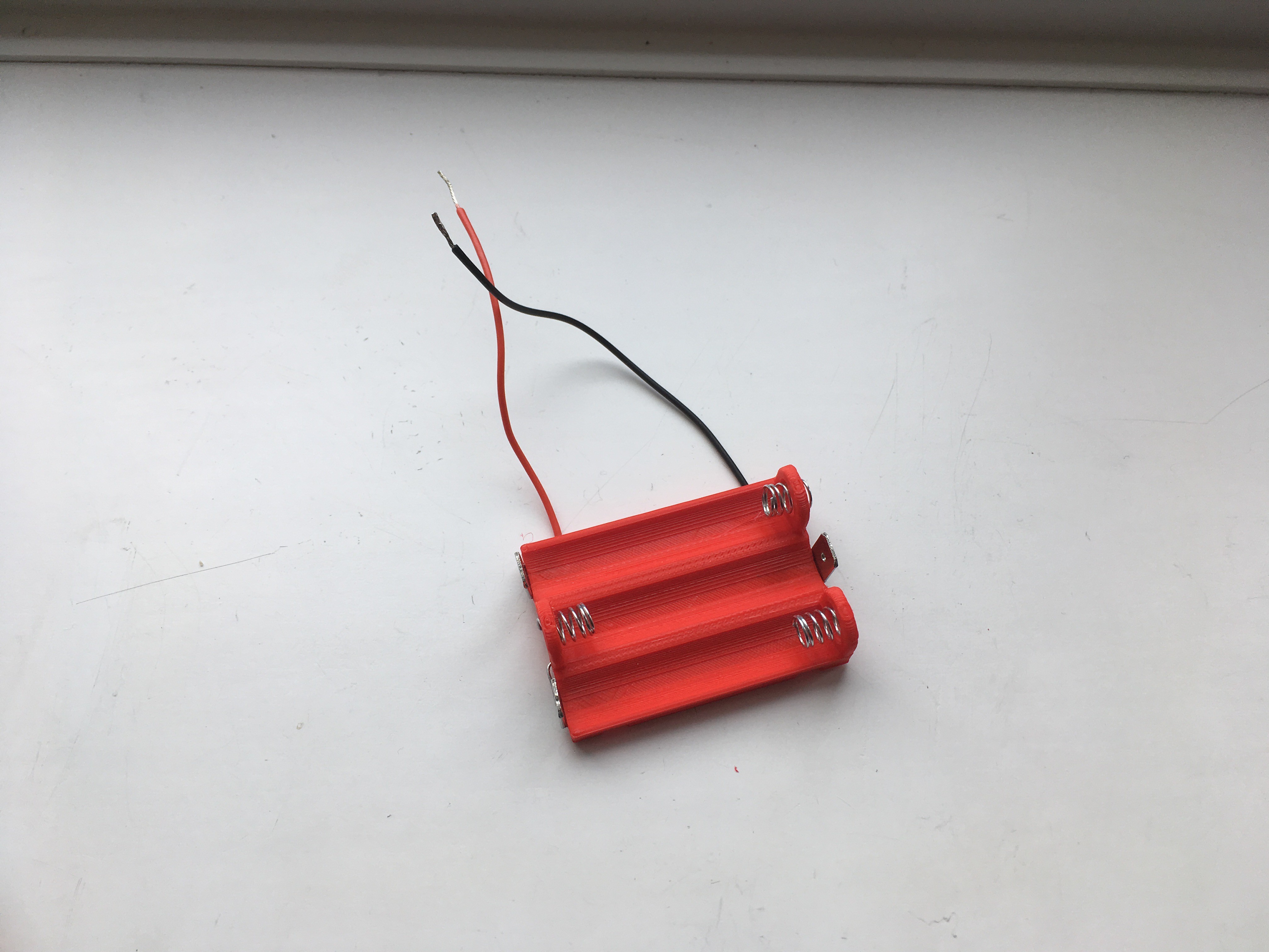
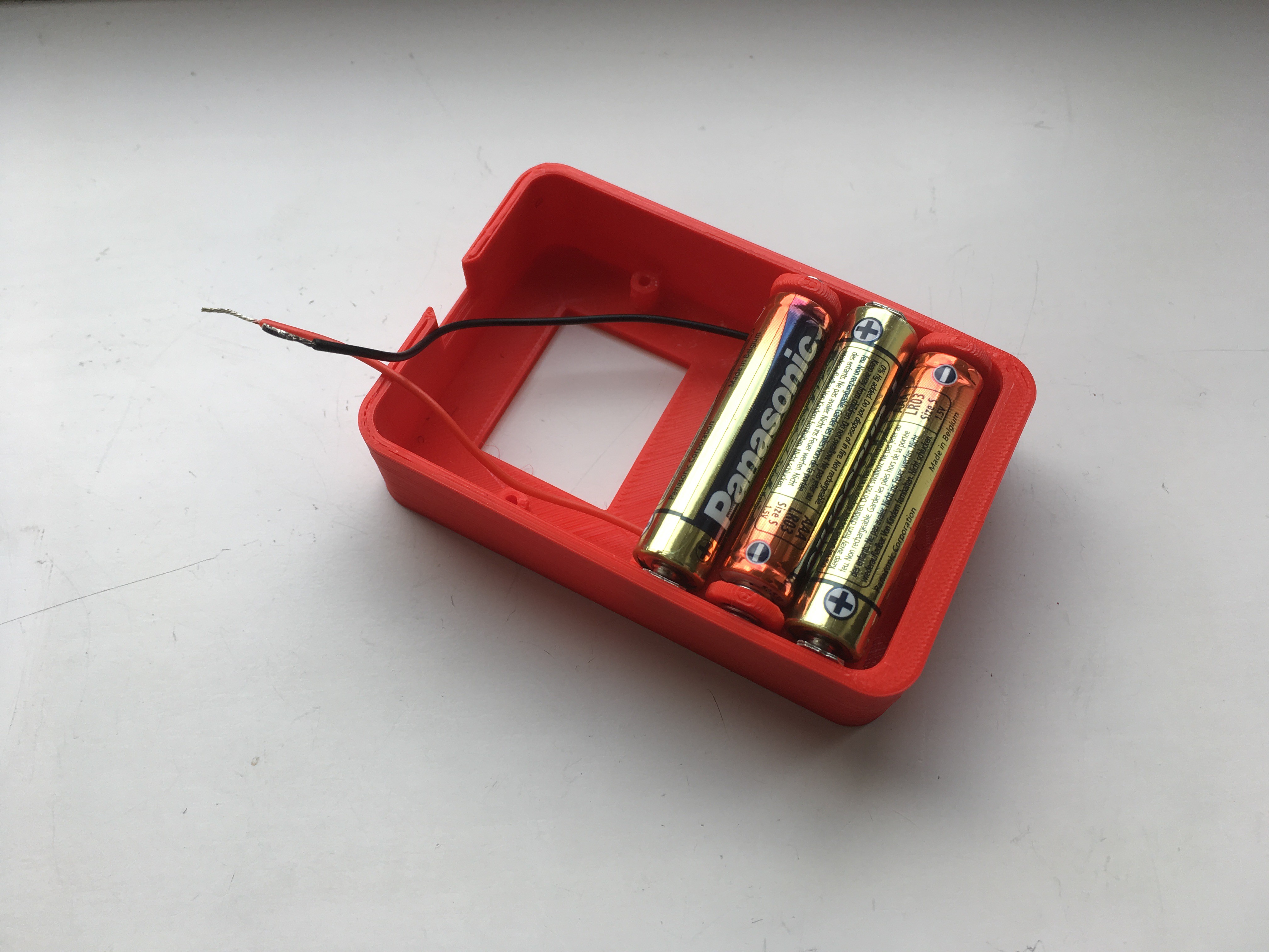
- 3x AAA batteries
- 4x M2 12mm screws.
- 4x M2 6mm screws.
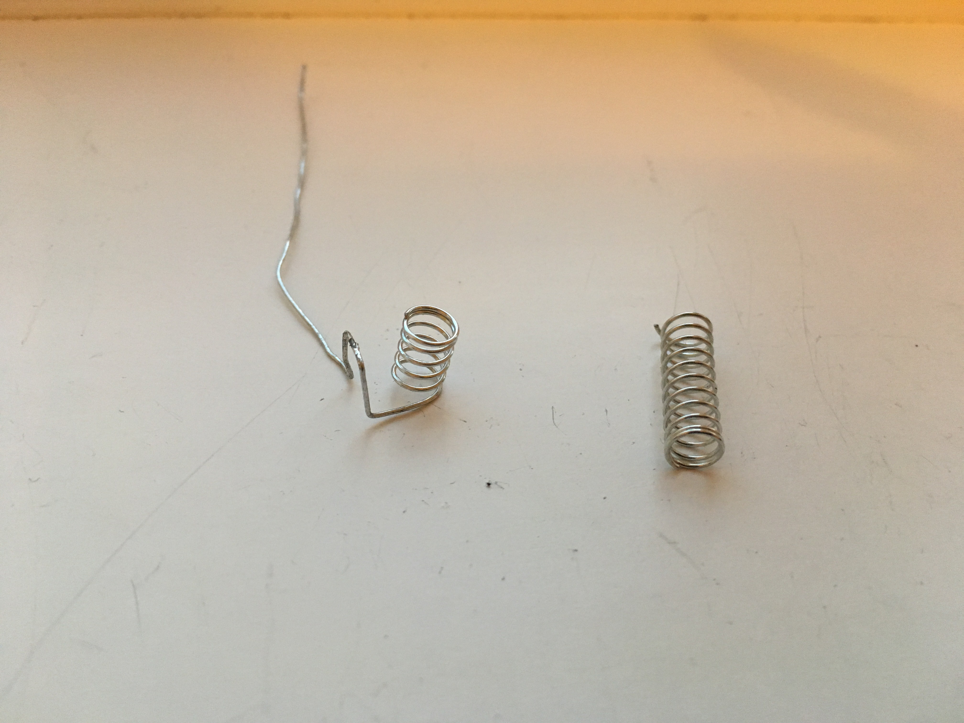
- 5mm compression spring to make the battery negative terminals from (See https://hackaday.io/project/26094-game-o-tron-mini/log/67402-11-power).
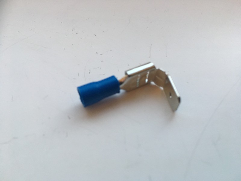
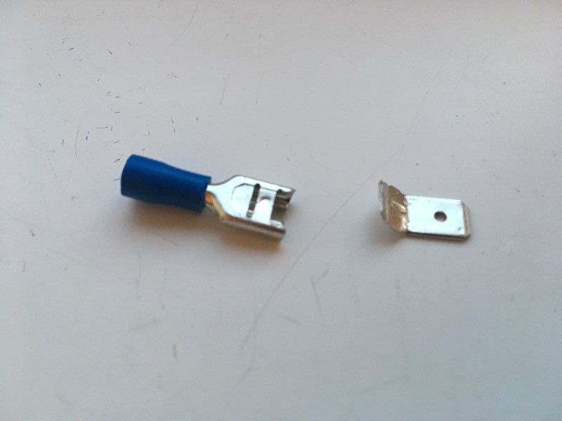
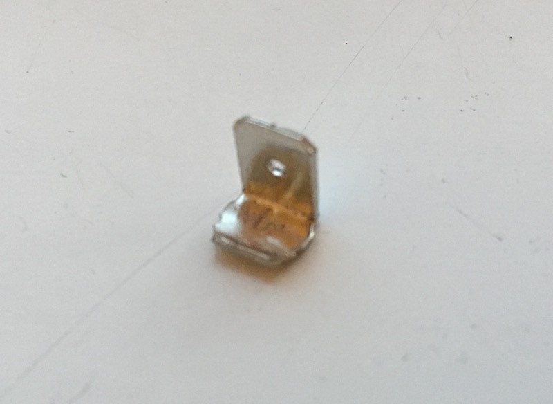
- Stackable spade connectors to make the battery positive terminals from (Again, see. https://hackaday.io/project/26094-game-o-tron-mini/log/67402-11-power).
- Perfboard, stripboard, wire and solder.
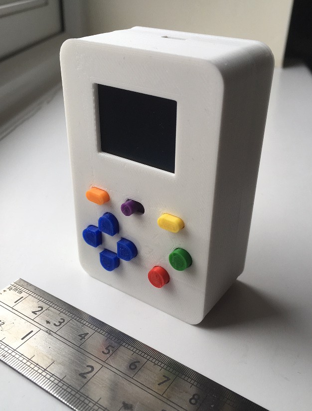
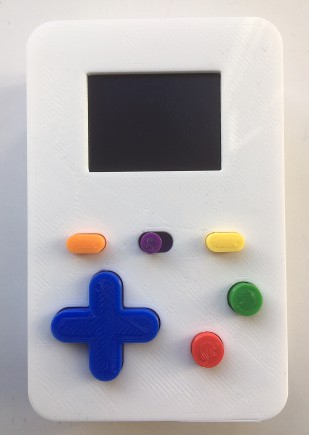
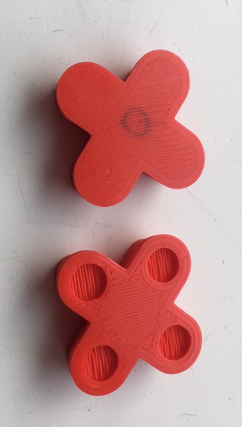
- Various 3D printed parts. The design files can be downloaded from http://8coloursound.org.uk/uploads/got_mini_printed_parts.tar.gz.


 lawnmowerlatte
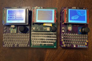
 Jorj Bauer
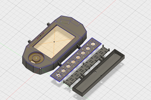

 Thornhill!
We got this for one of our clinics and our waiting patients enjoy using it while they wait for their turn. Our services can be found here: https://albanychirocare.com