David Boucher
-
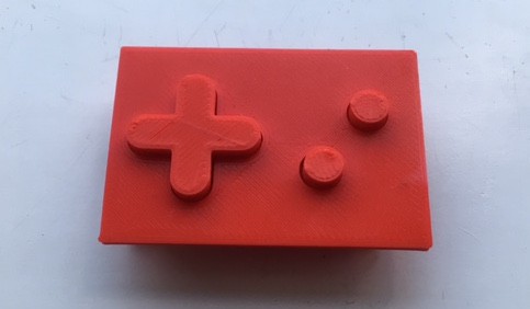
#9 - Final Front Layout
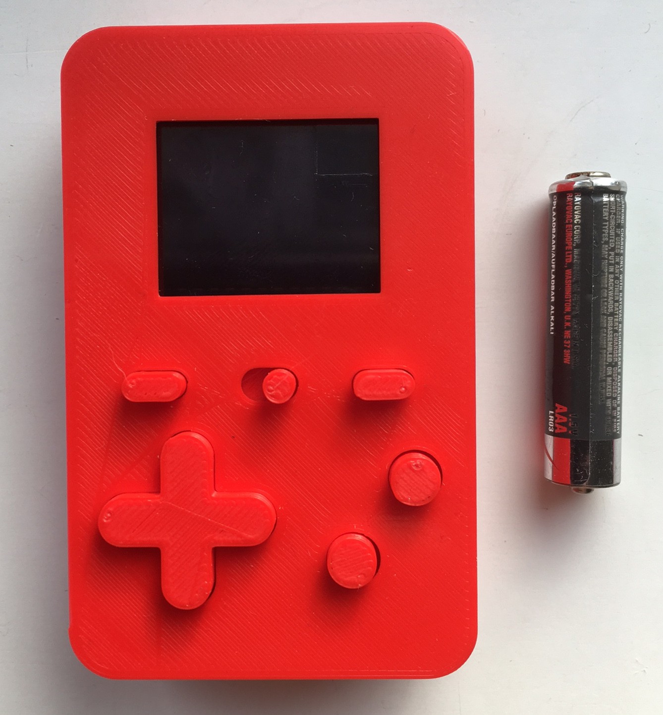
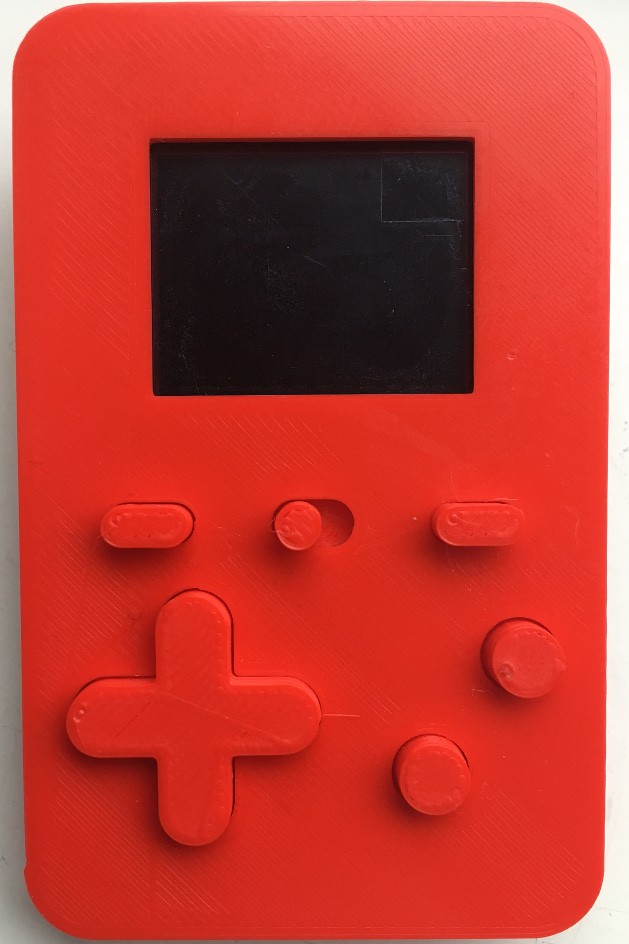
08/28/2017 at 19:19 • 0 commentsI've now finished the layout of the front and printed a new test piece:
![]()
Barring any major problems, this means that the layout of the controls, the positioning of the screen, and the overall dimensions are set in stone. The piece above also has the speaker and amplifier fitted as discussed in a previous log.
That said, there is one things that I am thinking of changing which is the screen mounting. The screen has four holes at the corners of its PCB and these sit over cylinders in the case front that hold the screen in position. Because these cylinders are quite small in diameter, they are fairly fragile. They also make the screen and Teensy carrier fiddly to fit.
The change that I'm thinking of making is to move these cylinders onto the Teensy carrier and remove them from the case front. This will mean that I can assemble the screen, Teensy and the carrier piece as one unit outside the case and then screw it into position. If I do this I probably won't need to print a new test piece as I can just snap the support cylinders off the current one.
In other news, I've started working in the graphics routines and looking at how to provide power, but those are matters for another log.
-
#8 - Graphics (Practice)
08/22/2017 at 20:13 • 0 commentsHaving worked out what how I wanted the graphics to work the next step was to implement it, which turned out to be fairly straightforward. Starting with the 16 bits per pixel, full colour framebuffer (see previous log), I wrote a program that would repeatedly fill the framebuffer with a random colour and then time how long in microseconds it took to transfer the framebuffer to the OLED.
The first version took the initialisation code from the Adafruit library and used a modified version of the screen clearing routine to transfer the data. This resulted in a figure of 26 FPS (Frames Per Second). Not terrible but not that great either.
One thing that I'd like to point out here: the Adafruit code is designed with a different goal to what I'm after, namely to be run on Arduinos that are very memory constrained. Therefore it has to write directly to the display as there's probably not going to be enough memory for a framebuffer. If it sounds like I'm knocking their code for poor performance that's not my intention and I'm glad they support their products in the way they do.
The first change that I made was seeing how high I could set the SPI frequency and get reliable operation. I found that this was 11Mhz; any higher than that and the transfer would sometimes fail part way through resulting in a partially filled screen.
After that I looked at the SPI transfer code itself. This uses SPI.transfer() and originally transferred a byte at a time but there are versions of SPI.transfer() that can do 16bit transfers and arbitrary length blocks of memory. Changing to a 16bit transfer gave me 34FPS and transferring a line of data at a time gave me 42FPS which I think is more than enough.
I also accidentally found out that if you use the version of SPI.transfer() that takes a memory buffer to transfer, it clears the buffer. I think that it's supposed to be filled with the data coming back from the device but as there is none in this case, and I don't have that pin connected anyway, I get all zeros. It does mean that I have to make a copy of the line of data I'll be transferring or the framebuffer gets cleared to black on each update. If this is something that you actually want you can take the copy out and get 43FPS.
Once I had the full colour version working, I wrote the palettised 256 colour version. That was slightly slower as it needs to do the palette to pixel colour conversion but still managed 40FPS.
Of course the graphics routines are far from finished, I will need code for drawing into the framebuffer and it might be possible to optimise the transfer further, but I'll leave those things for another log.
-
#7 - Graphics (Theory)
08/20/2017 at 17:40 • 0 commentsThe display that I am using is an OLED with an SSD1351 controller on a breakout board from Adafruit (here's a link: https://www.adafruit.com/product/1673). Adafruit also supply libraries and example programs to use it with an Arduino, and with a few minor tweaks these will work with a Teensy.
The libraries provide a basic set of graphical functions for drawing lines, boxes, circles etc, and these are drawn directly into to the display. For example, to draw a filled box, the library routine sets the drawing position to the top left hand corner and draws the top horizontal row of pixels. It then repositions to the left hand side of the box again, one row below the top, and draws the next row and so on until the box is complete.
The problem with using this approach with games with a lot of animation is that it would cause a lot of flicker as things are drawn and redrawn in various parts of the screen. The traditional solution to this in games is to use double buffering, where one frame of animation is shown on the screen whilst a second frame in another part of memory is updated. Once this new frame is complete the two buffers are swapped and the one that was being displayed can be redrawn before the buffers are swapped again, completing the cycle. This way, the player will never see a partially redrawn frame.
The display that I am using does not have the facility of an off-screen buffer so I can't do this, but there is an alternative that I can use which is almost as good. What I will do is instead of drawing directly to the display's memory, I will construct the frame in the SoC (Teensy's) memory. Once the frame is complete I will transfer it in one go from the SoC to the display. This will reduce flickering as much as possible albeit at the cost of some memory.
The OLED is 128x96 pixels and each pixel's colour is stored as two bytes. This means that the memory required to store a whole frame is 128 x 96 x 2 = 24576 bytes or 24Kb. Another option would be to use a palletised system where, instead of storing the colour value of each pixel, we store an index into a palette table which in turn stores the actual colour. For example, using a byte for each pixel would give us 256 colours and the memory usage would be 128 x 96 = 12288 bytes or 12Kb for the frame buffer and 256 x 2 = 512 bytes for the palette.
At this point I have not decided which approach to go for, although implementing both would be very easy. The Teensy has 64Kb of RAM, so even using the full colour frame buffer would leave plenty of memory left for other things.
-
#6 - Speaker and amplifier
08/13/2017 at 20:09 • 0 commentsNow that I have the display and controls in place I've been working on the positioning of the speaker and amplifier. The ideal place for the speaker would be on the front so that sound is directed straight at the player. I don't quite have enough space for that and I don't want to increase the overall dimensions. I do however have just enough space to accommodate the speaker along the bottom with the amplifier (this is the one I am using https://www.adafruit.com/product/2130) alongside it.
To test this out, I've printed another test piece of the bottom front of the case. I've increased the thickness of the bottom (without increasing the overall dimensions) to create recesses for the speaker and the amp which are held in place by a small clip attached to perfboard for the controls. This is what it looks like:
![]()
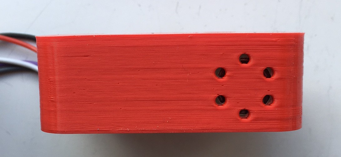
Here you are looking at the bottom of the case from the inside. The long screws with nuts are there because I didn't have any of the right length handy. I'll cut some down for the final version. This is what it looks like from the outside:
![]()
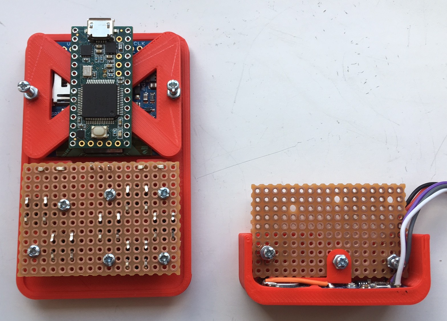
Finally, here is a side-by-side comparison of the front test piece with the display and controls fitted (but not wired up) with this one. I've also dropped a Teensy on there to show where it will go:
![]()
I also wired the speaker and the amp up to check that they work like this and that the wiring fits. My tests were successful, so next stop: Teensy.
-
#5 - How many buttons?
08/08/2017 at 19:05 • 2 commentsUp to now, my test prints have had two a Dpad and two buttons. I want to reserve these two buttons purely for actions in games such as jump and fire, so I need to think about what else I might need.
The most obvious thing is a power switch. I also want a way to change the volume, and possibly other settings in game. This would be a button that you could press at any time that would break out of the game you were in and change the settings using the Dpad and an action button. Pressing the button (let's call it the option button) again would return you to you game at the point you broke off. Another possibility would be to forget the options screen and just have two buttons for volume up and down.
To this end, my latest test add a power switch and a couple of extra buttons:
![]()
I've moved the gaming controls slightly lower down to make space and mounted the switch and buttons on perfboard in the same way as the others. The switch is a simple SPDT affair and the buttons are this type: https://www.coolcomponents.co.uk/en/tactile-switch-buttons-6mm-slim-x-5-pack.html. I went with the two button option in the interests of symmetry and also to make sure that two buttons would fit. I'm not sure that I'll keep it this way and might just have the one button next to the power switch.
-
#4 - A quick word on 3D printing
08/03/2017 at 19:35 • 0 commentsI thought I would briefly cover how I am making the 3D printed parts for this project.
I'm using OpenSCAD (http://www.openscad.org/) to design the parts. This allows me basically design by programming (going with what I know here). To give you an example, this is a very simple OpenSCAD program to create a 5mm cube with a 2mm diameter hole through it:
$fn = 100;
difference() {
	translate([-2.5, -2.5, 0])
		cube([5, 5, 5]);
	cylinder(r = 1, h = 5);
}
Which produces this:
![]()
Once I have a model to print, I export it from OpenSCAD as a .stl file and load it into Cura (https://ultimaker.com/en/products/cura-software) for slicing. I used to use Slic3r (http://slic3r.org/) but I find I get slightly better results with Cura. This gives me a .gcode file that I can transfer to the printer by SD card.
The printer itself is a BQ Hephestos (https://www.bq.com/en/hephestos-prusa), Prusa i3 variant that I've modified to replace the Z axis threaded rods with lead screws.
I will be making the OpenSCAD files available for download under some sort of free licence when I've finished the project.
-
#3 - Dpad and buttons
07/31/2017 at 20:09 • 0 commentsI've been working on the dpad (direction pad) and buttons, but mainly the dpad.
There are a number of different ways to do this, the simplest being to have four separate buttons for up, down, left and right that are directly exposed to the front panel. This would be very easy to build but has a couple of disadvantages in that you need to take your thumb off one button and to press another and also pressing diagonals is awkward.
I've decided to go for a traditional dpad which allows the player to change direction without lifting their thumb. The configuration is four switches with rubber tops (these: https://thepihut.com/products/adafruit-soft-tactile-button-8mm-x-10) arranged for up, down, left and right and mounted on perfboard. Wedged in the space between the switches is a small 3D printed pyramid which is a pivot which stops left and right or up and down being pressed at the same time.
The dpad itself sits on top of this and is a plus shaped part. This had a rim at the base which traps it between the case and the buttons. The whole thing is screwed to the case front with cut down M2 screws. The two action buttons are a simplified version of this with one switch and a 3D printed cap. In the final version these will be colour coded.
Here are the parts:
![]()
And the assembled article:
![]()
This took a few tried to get everything the right size to work well. The dpad has to have enough movement so that each direction can be pressed down and close the switch but not so much that it rattles. Also the pyramid pivot has to be high enough to stop opposite directions being pressed together but if it's too tall the dpad can't move properly. The rubber topped switches work well here as they hold the dpad in place when not being pressed but allow it to tilt without closing the switch. These switches have to be pressed all the way down before they close.
The end result, whilst not as good as a professionally made dpad, works well and there is still scope for some fine tuning.
-
#2 - Sound Check
07/28/2017 at 18:17 • 0 commentsAs I want this thing to be as small as possible, I wanted to see if the analogue output of the Teensy (the A14/DAC pin) would drive a small 8ohm speaker (one of these: https://www.rapidonline.com/Catalogue/Product/51-7389) without an additional amplifier.
To find out, I wrote a short program to send a sawtooth wave at roughly 440Hz to the analogue out. Here is the program:
/**
 * Sound Check
 *
 * Produce a sawtooth wave on
 * the Teensy's analogue out.
 */
#include "Arduino.h"
void setup()
{
    analogWriteResolution(8);
}
void loop()
{
    int level;
    for (level = 255; level >= 0; level--) {
        analogWrite(A14, level);
        delayMicroseconds(8);
    }
}
Connecting a speaker produces a sound that is audible but fairly quiet. I think that this would work for a earphone but not for what I wanted to do.
I next tried it with an amplifier. This was an Adafruit break out board based around a MAX98306 chip (https://www.adafruit.com/product/987). This is probably not what I will end up using as it is stereo and I only need mono but is suitable for a test and has adjustable gain. Using this, the sound is easily loud enough on the lowest gain setting.
Conclusion: amplifier required.
-
#1 - PlatformIO
07/26/2017 at 19:27 • 0 commentsUsually, developing for one of the Teensy boards involves installing the Arduino IDE (https://www.arduino.cc/en/Main/Software) and then installing Teensyduino (https://www.pjrc.com/teensy/teensyduino.html) on top of that to add Teensy support. There's not really anything wrong with that, but I don't like the Arduino editor and prefer to use my own choice of editor and compile and upload from the command line.
In the past I have done this by extracting the relevant files from an Arduino/Teensyduino install and writing a custom makefile. Since version 1.5 of the Arduino IDE, there is also the option of compiling from the command line without making any modifications (see https://playground.arduino.cc/Learning/CommandLine).
A few months ago, I discovered PlatformIO Core (http://platformio.org/), which takes the strain out of setting up a build environment for Arduino, Teensy and a lot of other micro controllers and IoT devices and this is what I will be using for this project.
To give you a simple example, here is what is needed for the classic "Blink" program:
- Create a directory for the project.
- Create a platformio.ini file. Using a Teensy 3.2 for our example, this would be:
[env:teensy31]
platform = teensy
board = teensy31
framework = arduino
(The Teensy 3.1 and 3.2 are functionally identical, so the 3.2 uses the same board specification as the 3.1)
- In the src subdirectory, create a main.cpp for the code:
/** * Blink * * Turns on an LED on for one second, * then off for one second, repeatedly. */ #include "Arduino.h" #ifndef LED_BUILTIN #define LED_BUILTIN 13 #endif void setup() { // initialize LED digital pin as an output. pinMode(LED_BUILTIN, OUTPUT); } void loop() { // turn the LED on (HIGH is the voltage level) digitalWrite(LED_BUILTIN, HIGH); // wait for a second delay(1000); // turn the LED off by making the voltage LOW digitalWrite(LED_BUILTIN, LOW); // wait for a second delay(1000); }- Finally, compile it and upload it with:
platformio run -t uploadThis will download the necessary files, compile the project and upload it, resulting in a Teensy with a blinking LED.
Of course, this is the simplest possible example, much more complex projects are possible and the PlatformIO site has full documentation on this. There is also a full IDE but I have not tried that.