Emma Barme
-
CRI and ZMQ
01/19/2018 at 16:04 • 0 commentsJust a short log to share excellent news: we have been discussing a collaboration with ZMQ, a "Technology for Development" social enterprise in India, for a few months now and we are officially kick-starting our working together on this project!
I am personally very excited to be working with Subhi, Ahmad and others from their IoT team as they have both a wonderful framework for developing system-changing approaches to address critical problems of poor, rural, under-privileged and unreached communities, and the technical skills to carry this project out.
If all goes well, we could have a full prototype by summer and start organizing tests with the future end users! -
Simplified companion device
01/19/2018 at 15:55 • 0 commentsAs stated in the previous log, we met with a design professor while in Shenzhen iSDG assembly and we left we new ideas for the design of the companion object.
The main driving concern about our previous design, a cube-shaped speaker with symbols on the side that could light up, was that it was not obvious how it should be used. Part of the problem is that symbols, while more understandable across cultures that written words, are far from universal. For example, how can we be sure that the standard occidental heart shape will be recognized as indicative of a cardiac problem by parents in rural areas in India?
We are now thinking of a button with a very simple shape, similar to that of a mushroom or a buzzer -see example below.
The buzzer would hold a speaker to sound an audio warning and give oral advice, as well as LEDs of different colors so the device can light up with a color corresponding to the level of emergency of the situation.
As the voice advice will be translated into local languages and adapted for each community, it would also be reasonable to adjust the emergency color coding to the standards of the community.
We believe that this design has a better chance to be easily interacted with by people from very different backgrounds than the previous one, though it of course needs to be submitted to the feedback of users.
All the electronic necessary to communicate with the sensors will also be hosted under the button.
For now we have identified only one big technical challenge with the new design: for the sound to carry out of the device, there should be holes in the button. However, it needs to be resistant to humidity and rain, so we need to find a way to protect the electronics properly.
-
Shenzhen iSDG assembly and new insights
08/31/2017 at 10:33 • 0 commentsAt the end of the CRI Labs Summer School, we were offered the opportunity to take part in the iSDG Shenzhen Assembly. The goal of this assembly was to gather students, researchers and makers involved in projects around the UN Sustainable Development Goals and "co-design innovative solutions for global sustainability".
With four other projects from the CRI Labs Summer School, we presented PreemieAlert during the assembly. We received a lot of positive feedback as well as interesting suggestions and questions that are going to feed our continued development. We also had the chance to interact with several mentors from very diverse fields.
In particular, a discussion with an experienced design professor led us to consider an entirely new design for our companion device. We will dedicated a specific log to this new idea, but it will roughly be a mushroom-shaped button with visual and audio feedback.
We also participated in a small workshop on how to establish a business model and will work on ours with the canvas from https://strategyzer.com.
-
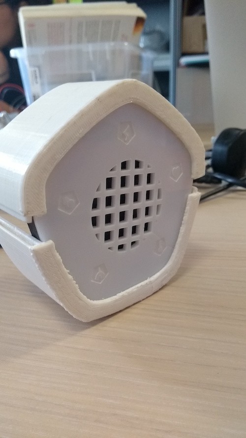
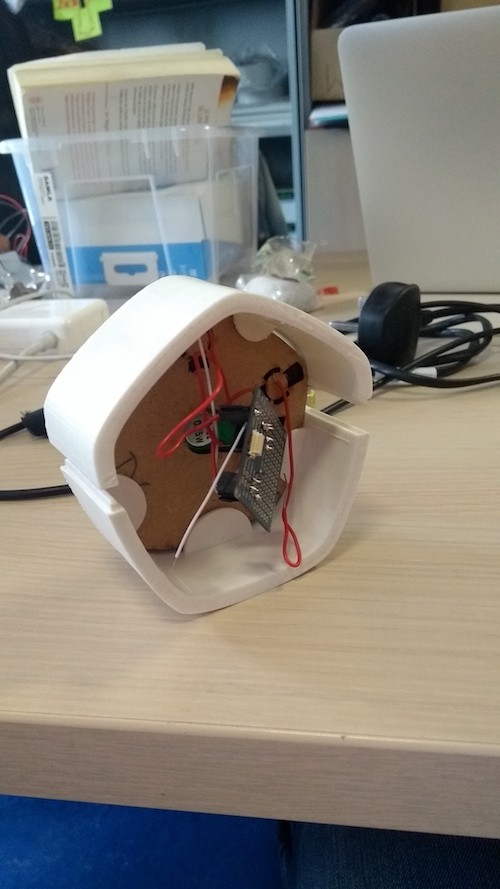
Layered companion device
08/09/2017 at 14:37 • 0 commentsShort update on the design of our companion device. It's composed of one layer of white plexiglass engraved with symbols, one layer of black paper with windows under the symbols, and two layers of wood to hold the LEDs, the speaker, and the wiring. Those layers are held together by a 3 printed plastic case (the one we have currently is slightly too small so we need to change the 3D model). The rest of the electronic (microchip, wifi, music shield, battery) fits in the case under the layers.
![]()
![]()
All the blueprints for laser cutting the layers and 3D models for printing the case have been uploaded on our Github.
-
General Representation
08/09/2017 at 13:05 • 0 commentsSchematic of the general process
Here is a global view of how the device works.
-
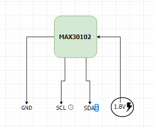
MAX30102-- how does it work?
08/08/2017 at 09:48 • 0 commentsThe MAX30102 uses a method called photoplethysmography to measure the heart rate of someone. This method shines light on the skin and the perfusion of the blood is measured. One of the practical aspects of this approach is that it is possible to differentiate between the light reflected by the blood of an artery (produces an AC output) and other components of the body such as bones and tissues (produces a DC output). The photo-diode in the sensor then converts the light to current that we can use as comprehensible data.
To counter difficulties such as skin tone differences LEDs with different wavelengths are used. In the MAX30102 there is an extra green LED for this purpose.

Another log will be posted later on to provide precision on how we calculate the SP02 and heart-rate from the AC output of the sensor.
-
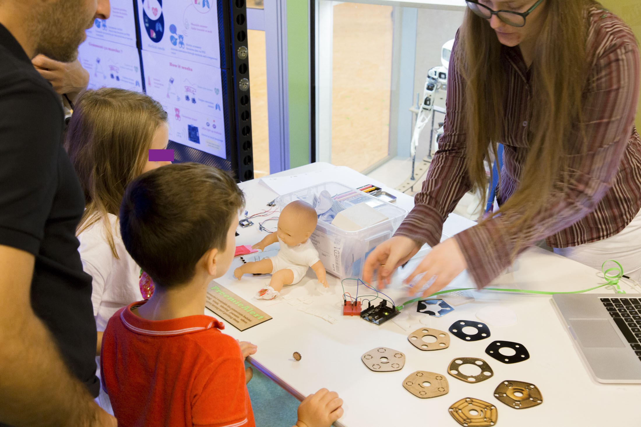
Exhibition in science museum
08/07/2017 at 10:56 • 0 comments![]()
We had a wonderful time on Friday at the Cité des Sciences et de l'Industrie, one of Paris's science museums. We presented our project among the others of the CRI Labs Summer School to invited scientists and curious families.
We received heart-warming compliments and encouragements, both on the project itself and on our presentation.Our posters from the exhibition have been uploaded here in the files.
We were able to show a working infrared temperature sensor. This allowed us to detect a problem: when the heat source stays on the sensor for too long the measurement becomes very imprecise.
We also showed the various steps of our prototyping and the electronic components we used. -
Heart Beat Sensor Update
08/07/2017 at 09:14 • 0 commentsThis is a follow-up on the previous post on the heart beat sensor MAX30102. The problem encountered previously was the death of the sensor with no explanations. We tested out a new sensor on the code and determined two possible causes.
Firstly, we based ourselves on code online which uses an Arduino with a 3.6V input. After reading the specifications we observed that the sensor can be submitted to a voltage of min 1.7V and max 2V with a suggested 1.8V input.
Secondly, the sensor should be tailored to the different skin and the location where we put the sensor. The intensity of the light emitted should be changed in order to find the best possible results. This needs to be experimented on to find the best solution.
-
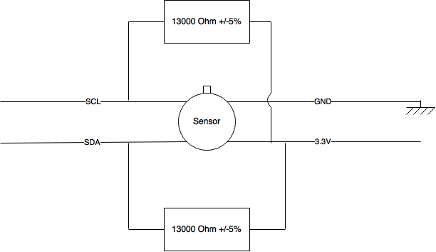
Working temperature sensor!
07/31/2017 at 09:10 • 0 commentsWe have received and wired our MLX90614 Temp Sensor.
We used the Adafruit library and you can find our code on our GitHub.
![]()
PreemieAlert
A frugal connected wearable to support caretakers in tending to premature babies #SDGclass2017